Cihaz
b--- title: Device Management System description: Device Management System Module User Help Document
sidebar_position: 1
Information
You can quickly reach the relevant topic with the help of navigation on the right side.
Device Management System Module (v.5.26) User Help Document
Module Version: 5.26
1. INTRODUCTION:
“QDMS Device Management System Module” covers the follow-up of activities such as calibration, maintenance and verification of the devices in a company; periodic maintenance and storage and reporting of the data generated as a result of these processes. In addition, the storage and updating of the device inventory is also within the scope of device management.
2. PURPOSE:
The purpose of this manual is to keep the device inventory up to date with the help of the Device Management module on QDMS, to determine the types of operations, to determine the operation periods for each device or device category and to determine the path to be followed when performing device activities and storing the relevant data as these periods arrive.
3. RESPONSIBILITIES:
Device Responsible (C), Process Responsible (I)
4. ABBREVIATIONS:
QDMS: Quality Document Management System
CAL: Calibration
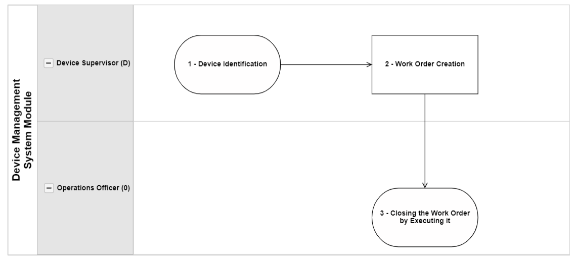
5. WORK FLOW:
6. Device Management System Module
It is a module that tracks device-oriented transactions such as calibration and verification, monitoring device inventories, instant access to calibration reports and history, informing device and process managers via e-mail, and tracking transaction costs. It is also the module where the device's status such as scrap, in use and defective is tracked.
This module includes the following features in its content.
- Ensuring the correction of errors by determining the deviations of the test-measuring instruments or devices used in measurement as a result of the calibration process.
- Determining the deviations of the devices as a result of calibration and ensuring the reliability of the measurement results when the accuracy of the devices is certain.
- Ensuring the categorization of the devices by determining the devices in general such as weight meters, pressure meters and length meters.
- Providing the process of defining the types of operations to be performed on the devices specific to the device category.
- Providing the process of defining the process locations in the system where the devices are subjected to external processes such as calibration.
- Providing the process of defining unlimited operation types such as calibration and verification.
- With the “Device Code Replacement” menu, it is possible to quickly change the code of the devices in the system one by one at the same time.
- With the “Device Maintenance” menu, it is ensured that the process of changing certain information of the devices collectively is realized.
- “Device Maintenance” menu enables the update of device information and transaction type information within the scope of the device management system.
- With the “Multiple Device Code Replacement” menu, it is possible to quickly change the codes of the devices in multiple ways at the same time.
- Providing the process of making system settings in line with the user's requests and needs.
- With the “Device Eraser” menu, it is ensured that the devices are deleted from the system so as not to be used.
- Ensuring the follow-up of device-related procedures such as calibration and verification.
- Providing the process of monitoring device inventories.
- With the “Define Device” menu, devices are introduced to the system and displayed in the device list according to the colors specified in the device status.
- With the “Define Device” menu, providing the process according to the status of the devices in the filter tab and search criteria such as operation type.
- Providing instant access to the information of the device according to the history of the operations performed on the device.
- Providing the process of uploading external calibration certificates and reports to the system.
- Providing access to the requested reports on planned and past calibrations.
- Ensuring the process of tracking the competency documents of external calibration companies.
- Opening work orders manually with the “Fulfill operation” menu and ensuring the process of automatically opening work orders.
- Ensuring that reminder e-mails are sent to the device responsible and the process responsible for the devices whose processing time is approaching.
- Ensuring the process of assigning tasks as “Devices to be processed” in my pending jobs for devices whose processing time is approaching.
- Ensuring that the devices are transferred in bulk at the same time and quickly without defining the devices one by one.
- Providing the process of defining the calibration report format template based on the device category.
- Providing the process of preparing the calibration report and viewing the prepared report with the “Calibration Report” menu.
- Providing the process of user-specific authorization on the basis of the places where the devices are defined.
- Ensuring that the e-mails of periodic work orders are sent collectively at one time.
- Ensuring that pre-notification e-mails determined for device realization operations are sent in bulk at one time.
- Ensuring that manual work order mails are sent in bulk.
- Ensuring that the calibration report is opened protected if it is not desired to allow changes to be made on the calibration report created in the system.
- Tracking transaction costs and providing the process of viewing them as a report.
- With the “Adding additional file” feature, it is possible to define the device and provide detailing in the process of performing the operation.
- With the “Planned Operation Report”, general information and dates of the planned operations are displayed and the report is obtained according to the desired criteria with the search tab.
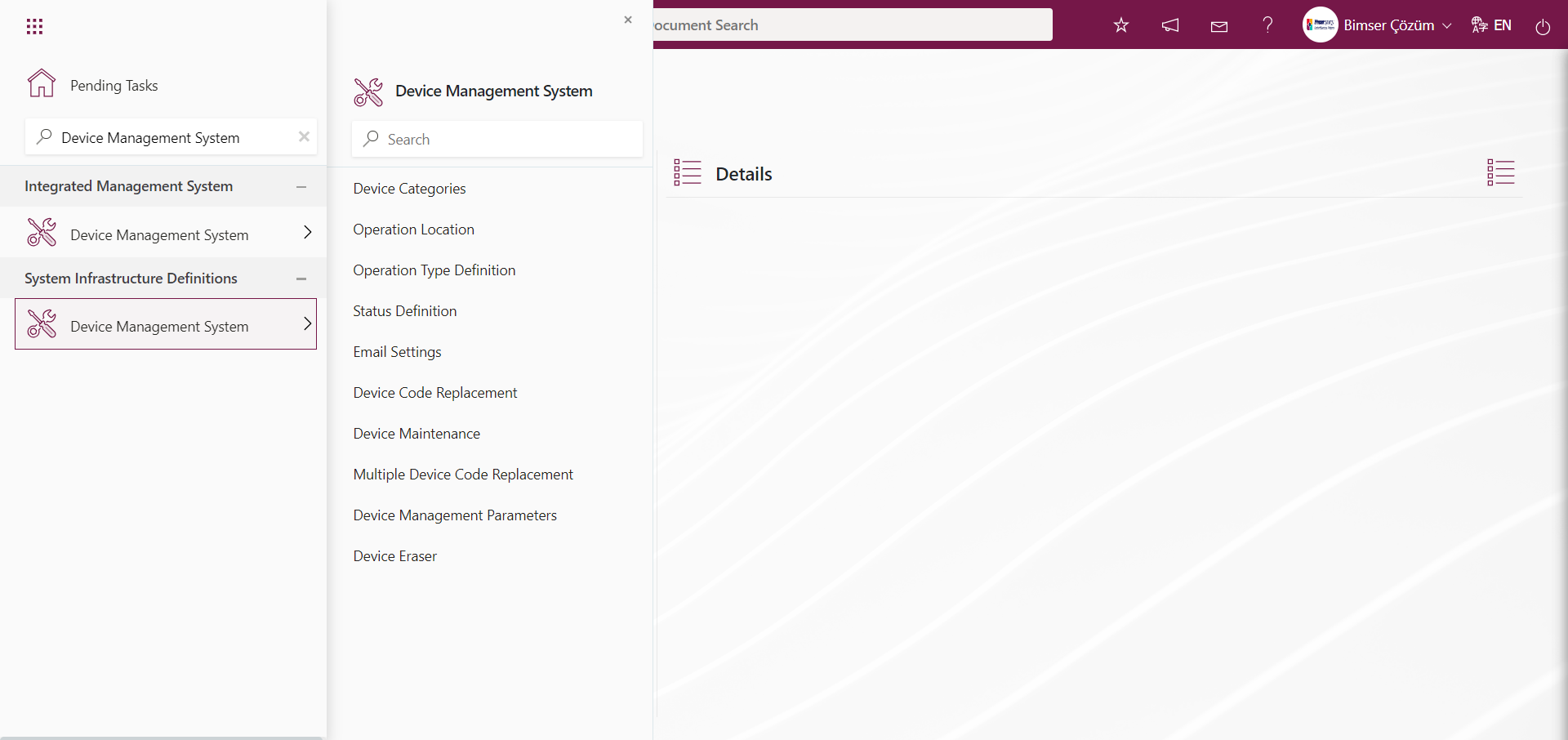
6.1. System Infrastructure Definitions/ Device Management System
This is the part where definitions are made to create the infrastructure of the Device Management System Module. Data appears according to the definitions made. Definitions that will form the infrastructure of the module such as Device Categories Definition, Operation Type Definition, Status Definition, Operation Location Definition are made in this section and data are used according to these definitions made in the Integrated Management System section of the module.
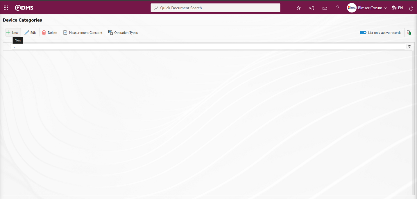
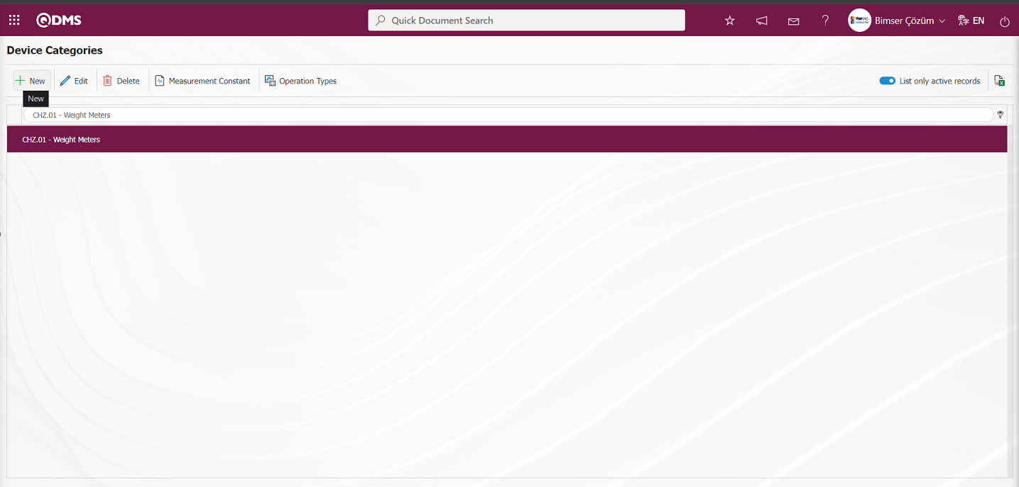
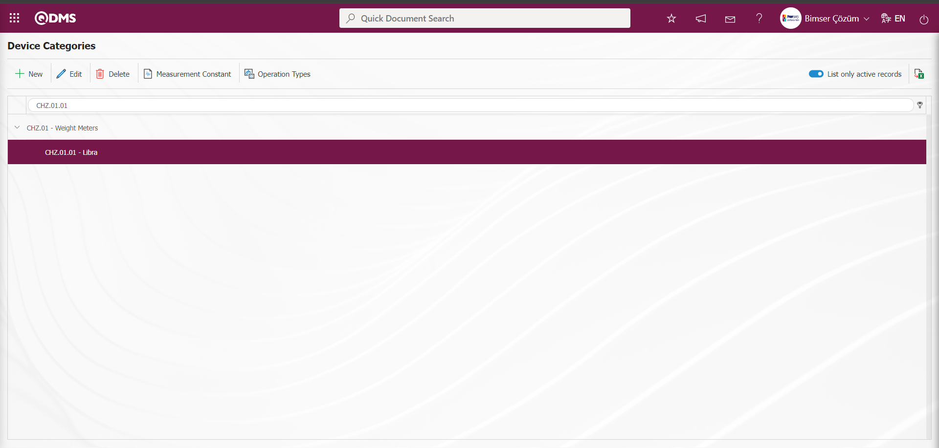
6.1.1. Device Categories
Menu Name: System Infrastructure Definitions/ Device Management System/ Device Categories
It is the menu where the categories of the devices to be used within the scope of the Device Management System module are defined. In this menu, devices are generally categorized by defining them as weight meters, pressure meters and length meters. For example, under the weight meters, scales and scales are categorized by defining the scales and scales in the form of tree breakdown
With the help of the buttons on the screen;
 : Defining a new device category is done.
 : Edit and update the device category information selected in the list.
 : Delete the device category information selected in the list.
 : Determining the measurement constants of the device category selected in the list.
 : The process of determining the operation types of the device category selected in the list is done.
 : When the check box related to the relevant field is checked, it is ensured that the records with active status are listed in the device category list.
 : Getting the report of the device category list in Excel format is done.
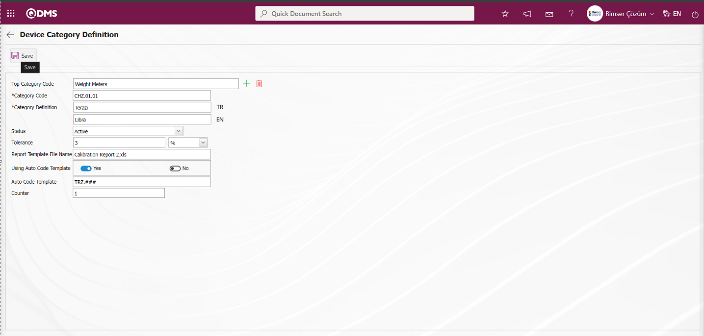
To add a new device category to the list, click on the button at the top left corner of the screen to display the Device Category Definition screen.
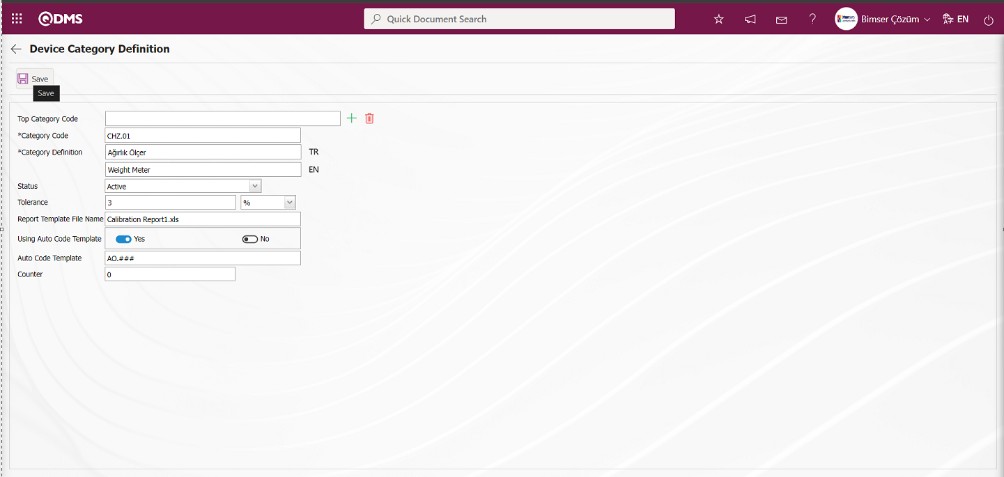
Related fields are defined on the screen that opens:
Top Category Code: The top category code, which is in the definition phase on the Device Category Definition screen, is saved to the system in advance as a category code definition. If there is a subcategory connected to this top category, this field is automatically filled. In the filled field, the name of the parent category code definition to which it is connected is written. If you want to delete the subcategory to which it is connected, use the  (Delete) button on the right side or if you want to change it, use the
  (Select) button on the right side. If there is no parent category to which it is connected, this field is empty.
Category Code: This is the field where the device category code information defined in the Device Category Definition screen is written.
Category Definition: This is the field where the name of the device category defined on the Device Category Definition screen is written. In the field with the English language equivalent icon, the English language equivalent of the definition part of the device category is written.
Status: This is the field where the status information of the device category defined on the Device Category Definition screen is selected in passive or active options.
Tolerance: This is the field where the tolerance value (%) of the device category defined on the Device Category Definition screen is written. It is the part that shows how much the percentage deviation will be accepted. When the acceptance lower and upper ranges are entered manually by the user, the system automatically calculates the lower and upper acceptance ranges according to the tolerance value.
Report Template File Name: This is the field where the report template file name and extension of the device category defined on the Device Category Definition screen are added. In this field, report template is added on the basis of device category. In order to add this report template to this field, you must first upload the report template in the System Infrastructure Definitions / BSID / Configuration Settings / Default Report Layouts Arrangement menu. After uploading the report template in the report formats editing menu, the name and extension of the uploaded report template are pasted into this field with the right-click/copy-paste method.
Using Auto Code Template: This is the field where “Yes” or “No” options are selected from the options related to the use of the automatic code template of the device category defined on the Device Category Definition screen. If it is desired to define an automatic code template related to the defined device category, the “Yes” option is selected by selecting the relevant radio button in this field.
Automatic Code Template: This is the field where automatic code template information is defined for the device category defined on the Device Category Definition screen, as in the Document Management module. It allows the use of automatic code template when defining device categories. In defining the device connected to this category, the system automatically assigns the device code according to the code template in the code field: AO.###
Counter: This is the field where the value of the counter of the device category automatic code template defined in the Device Category Definition screen is written if the counter is desired to start from how many.The code counter is the part that automatically counts the device categories based on the ### expressions in the automatic code template. For example: When the counter value “0” is entered according to the AO.### automatic code template, the system allows the devices defined depending on the defined device categories to be automatically coded from AO.000 to AO.999 in order. Unlike in the Document Management module, the code template does not start by increasing the counter value by “1”, but starts from the value of the code template counter value.
Top Category code information can be selected from the list of categories defined in the system. Device category definition and code information is written. Status information is divided into two as “active” and “passive”. Actively defined device category refers to the device categories used in the system. If a device category definition is no longer used in the system, its status should be changed to “inactive”. In this way, both the existing records in the past will not be affected and the inactive device category information will not be displayed on the new device category selection screens. The status of the device category is selected as active. Tolerance value (%) information is entered. Automatic code template information “Yes” option is clicked. After the required fields are filled, the device category definition registration process is done by clicking the  button in the upper left corner.
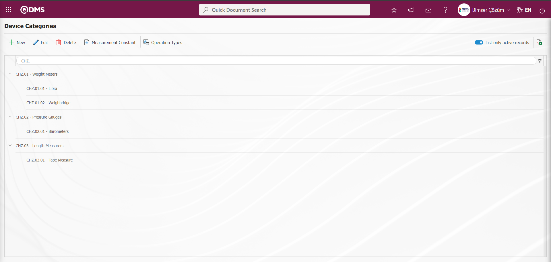
To add a new subcategory to an existing device category, while the device category to be subcategorized is selected, go to the device category definition screen with the button.
In the Device Category Definition screen, the upper category code is automatically filled. After the subcategory is created and the necessary fields are entered, the Device Category definition registration process is done by clicking the button in the upper left corner of the screen.
On the Device Categories Definition screen, categories and subcategories related to device categories are defined in the same way. On the Device Categories Definition screen, device categories can be defined in the form of tree breakdown as many times as desired.
The “Tolerance ” field is a shortcut field where you can set limits by giving % values to the lower and upper ranges in the measurement constants field according to the device category. In the “Report Template File Name” field, the name and extension of the report formats determined according to the device categories in the Default Report Layouts Arrangement menu are written together. In this way, the calibration report will vary according to the device categories.
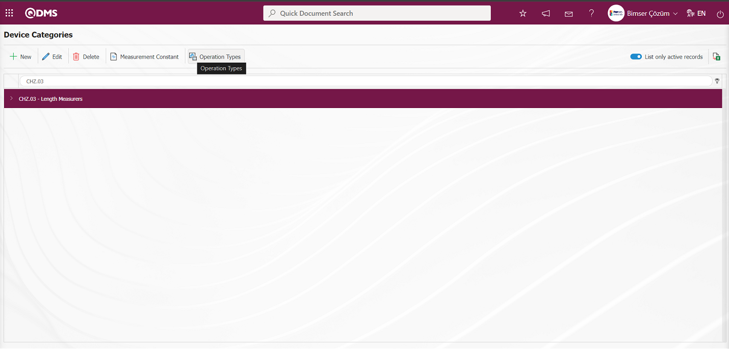
On the Device Categories screen, click the  button while any category is selected in the list.
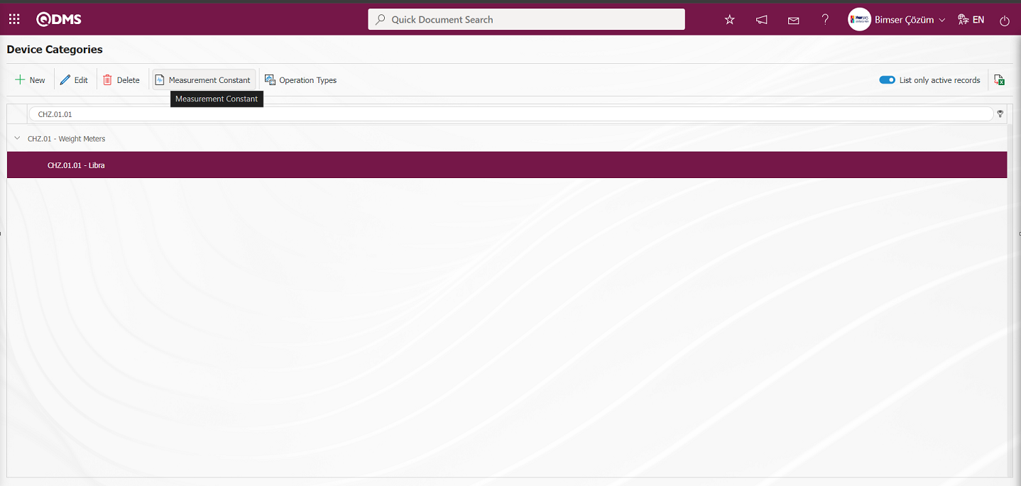
Opens to the Measure Constants screen.
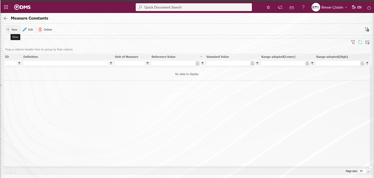
With the help of the buttons on the screen;
 : Defining a new measurement constant is done.
 : Edit and update the selected measurement constant information in the list.
 : Delete the selected measurement constant information in the list.
 : Return to the previous screen.
 : Data can be exported to Excel.
 : The search criteria on the menu screens are used to clean the data remaining in the filter fields in the grid where the search operation is performed.
 : The menu screen is restored to its default settings.
 : User-based designing is done on the menu screen with the show-hide feature, that is, the hiding feature of the fields corresponding to the columns on the menu screens.
Defining Measurement Constants by Device Category;
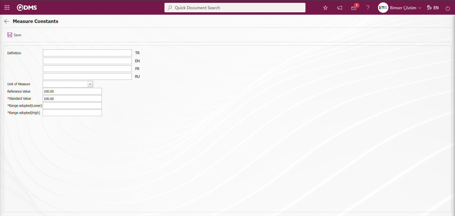
To add new measurement constants to the list, the Measurement Constants screen is displayed by clicking the button in the upper left corner of the screen.
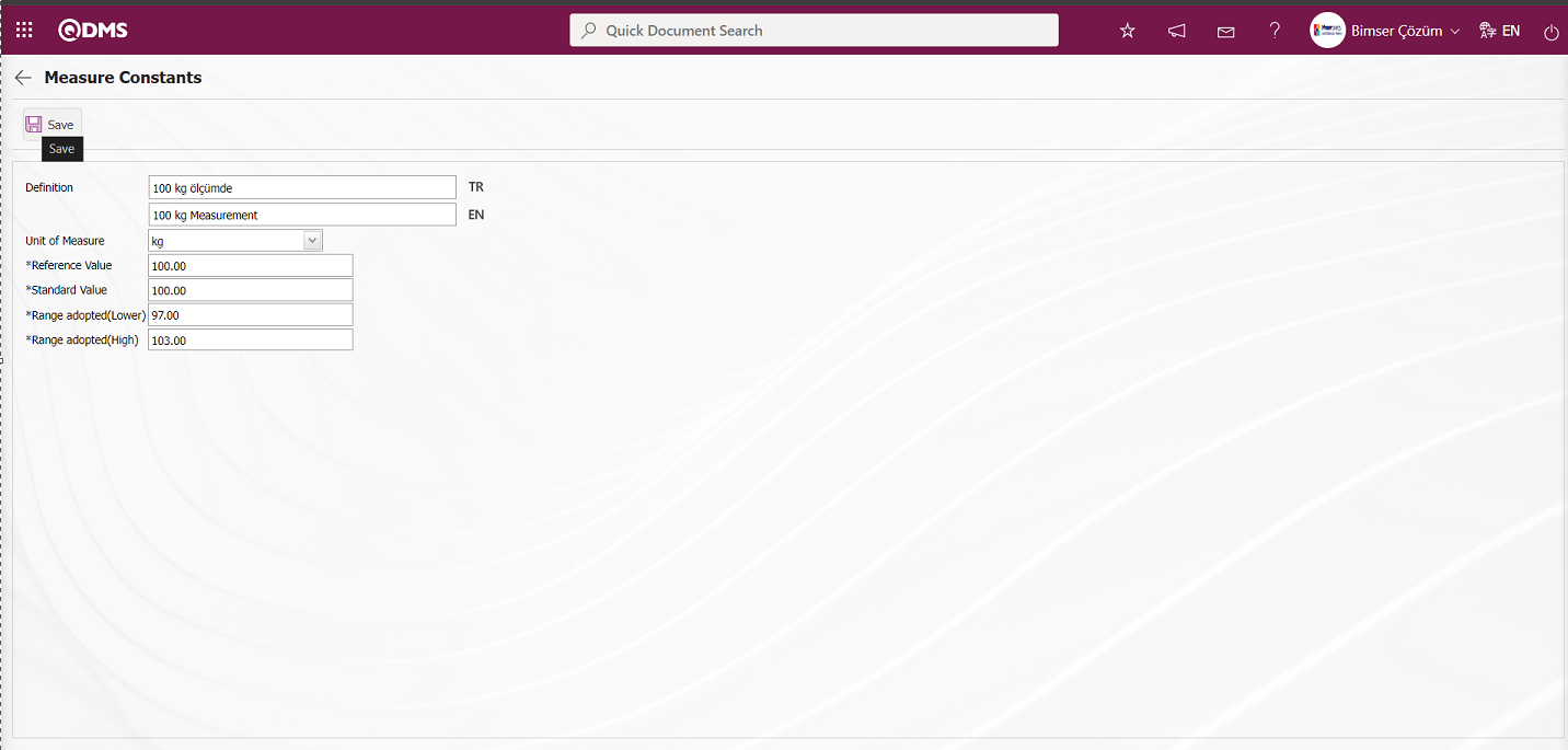
Related fields are defined on the screen that opens:
Definition: This is the field where the definition information of the measurement constant defined in the Measurement Constants screen is written.
Unit of Measurement: This is the field where the unit information of the measurement constant defined in the Measurement Constants screen comes to the System Infrastructure Definitions/BSID/ Definitions/ Unit of Measurement Definition menu. The defined units of measurement in this menu appear. If you want to define a new measurement unit, it should be defined from this menu. For example Pieces, Kilograms
Reference Value: This is the field where the reference value information of the measurement constant defined in the Measurement Constants screen is written.
Standard Value: This is the field where the standard value information of the measurement constant defined in the Measurement Constants screen is written.
Range adopted(Lower): This is the field where the system calculates the range of acceptance lower information of the measurement constant defined in the Measurement Constants screen.
Range adopted(High): It is the field where the upper acceptance range of the measurement constant defined in the Measurement Constants screen is calculated by the system.
Enter the definition information of the measurement constant. The unit of measurement of the measurement constant is selected from the options defined in the system. Reference and standard value information is entered. The system automatically calculates the upper and lower acceptance range according to the tolerance value given in the device category definition screen. After the required fields are filled, the  button in the upper left corner is clicked and the measurement constants definition registration process is performed.
The parameter is activated by selecting “Yes” for parameter 52 in the Device Management System module parameters.
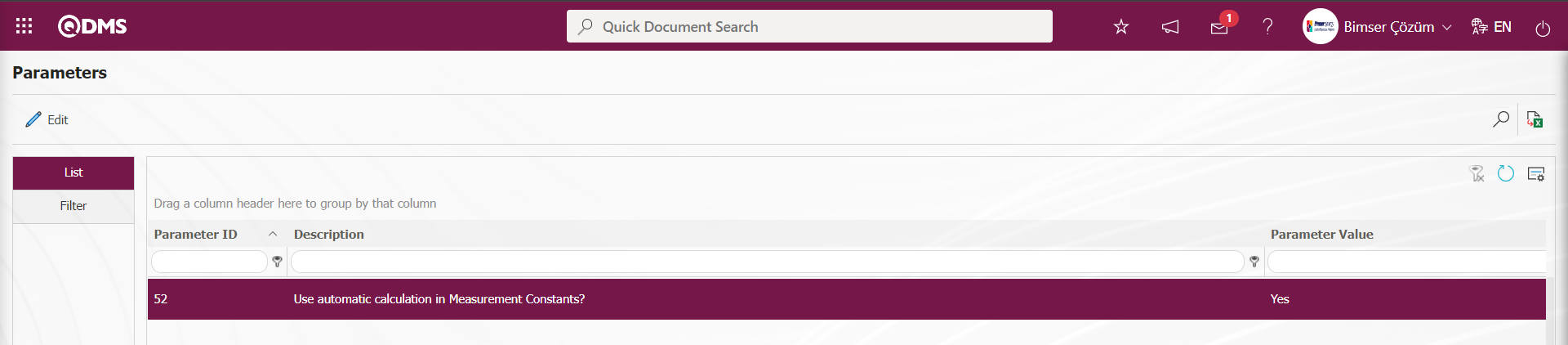
After the parameter is activated, the calculation process on the Measurement Constants screen is done automatically by the system. When the parameter is disabled by selecting the parameter value “No”, the calculation process on the measurement constants screen is allowed to be done manually manually.
According to the numerical value entered in the parameter value of parameter 57 in the Device Management System Module parameters, it is determined how many digit values (number of digits) will be entered after the comma in the numerical values written in the measurement values. 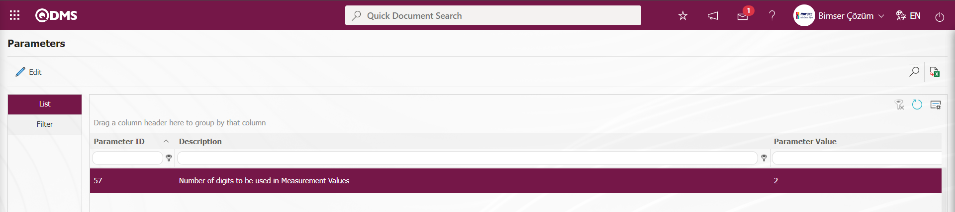 In parameter 57, the number of digits is defined as “2” in the parameter. In the figure below, the digit value after the comma entered in the Measurement Values screen is limited to 2 according to the digit value defined in parameter 57.
Users can define the number of digits after the comma after the numeric values written in this parameter as they wish.
Defining Operation Types Based on Device Category: Pre-determined operation types can be assigned to the relevant category with the  button on the Device Category Definition screen.
For Defining Operation Types Based on Device Category, click the button while the operation type is selected in the list.
The Operation Types in Categories screen opens.
With the help of the buttons on the screen;
 : Defining the operation type of a new category
 : Changes and updates are made on the operation types belonging to the selected category in the list.
 : Delete the operation type information belonging to the selected category in the list
 : Returns to the previous screen.
 : Data can be transferred to Excel.
: The search criteria on the menu screens are used to clean the data remaining in the filter fields in the grid where the search operation is performed.
: The menu screen is restored to its default settings.
: User-based designing is done on the menu screen with the show-hide feature, that is, the hiding feature of the fields corresponding to the columns on the menu screens.
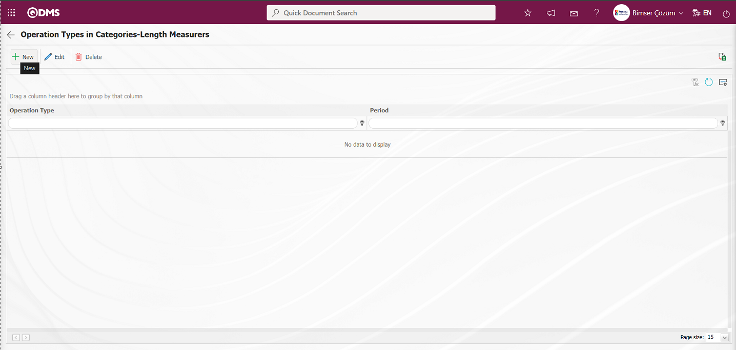
To add a new category sub-operation type to the list, click button in the upper left corner of the screen and the Category Suboperation Types screen is displayed.
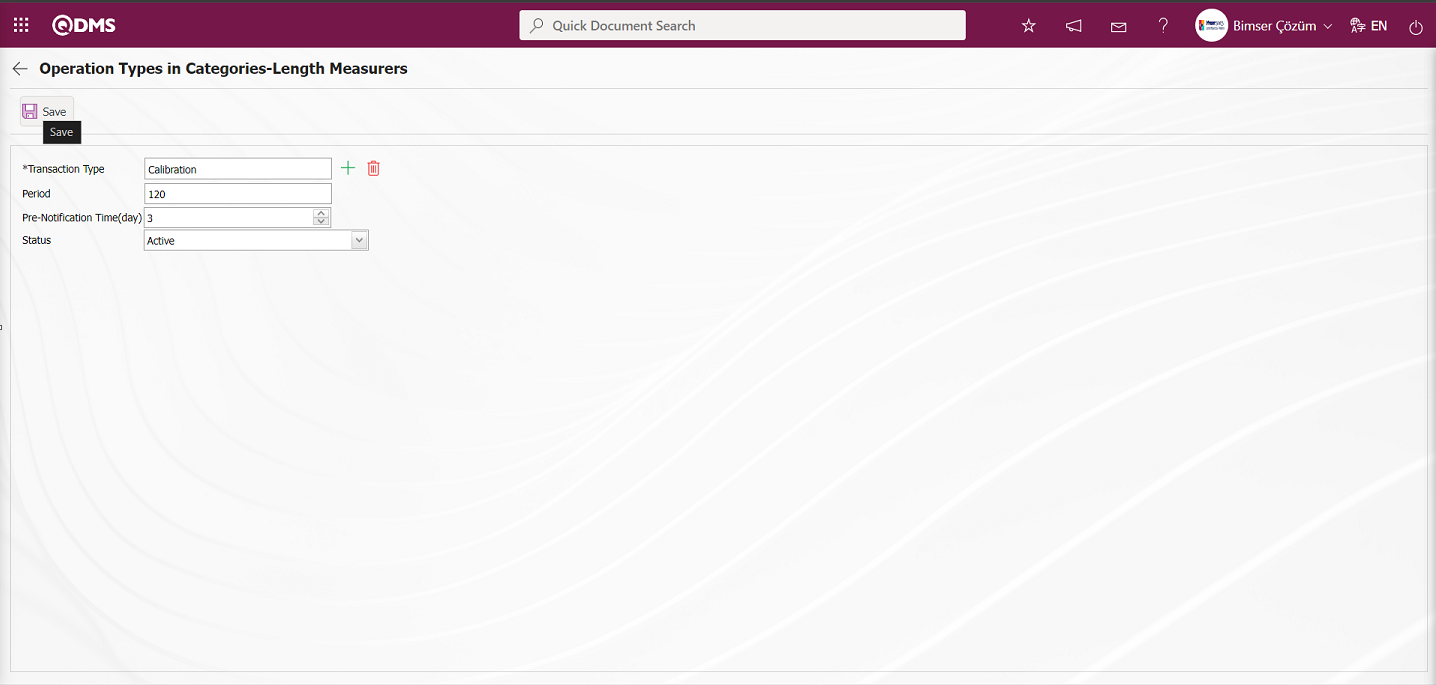
Related fields are defined on the screen that opens:
Transaction Type: This is the field where the transaction type of the category is selected from the list of transaction types defined in the system opened by clicking the  (Select) button on the Transaction Types of the Category screen. Operation Type list comes as defined in the System Infrastructure Definitions / Device Management / Operation Types Definition menu.
Period: It is the field where the period information of the operation types of the category defined in the Operation Types of the Category screen is written. Calibration period definition is made on the basis of day and month according to the value written in parameter 10 in the Device Management System Module parameters.
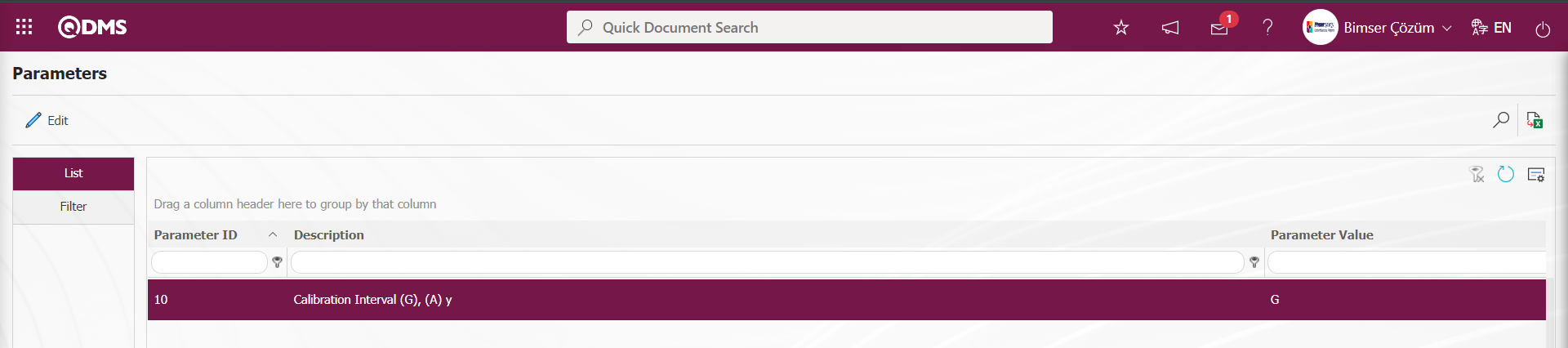
To set the calibration period on day basis, the letter “G” is written to the parameter value in parameter number 10. If you want to set the calibration period on a month basis, the letter “A” is written to the parameter value in parameter 10. According to this adjustment made in the parameter, the value is entered in this field on a day and month basis.
Pre-Notification Period (days): This is the field where the pre-notification period information of the transaction types belonging to the category is written in days.
Status: It is the field where the passive or active status of the transaction types belonging to the category is selected.
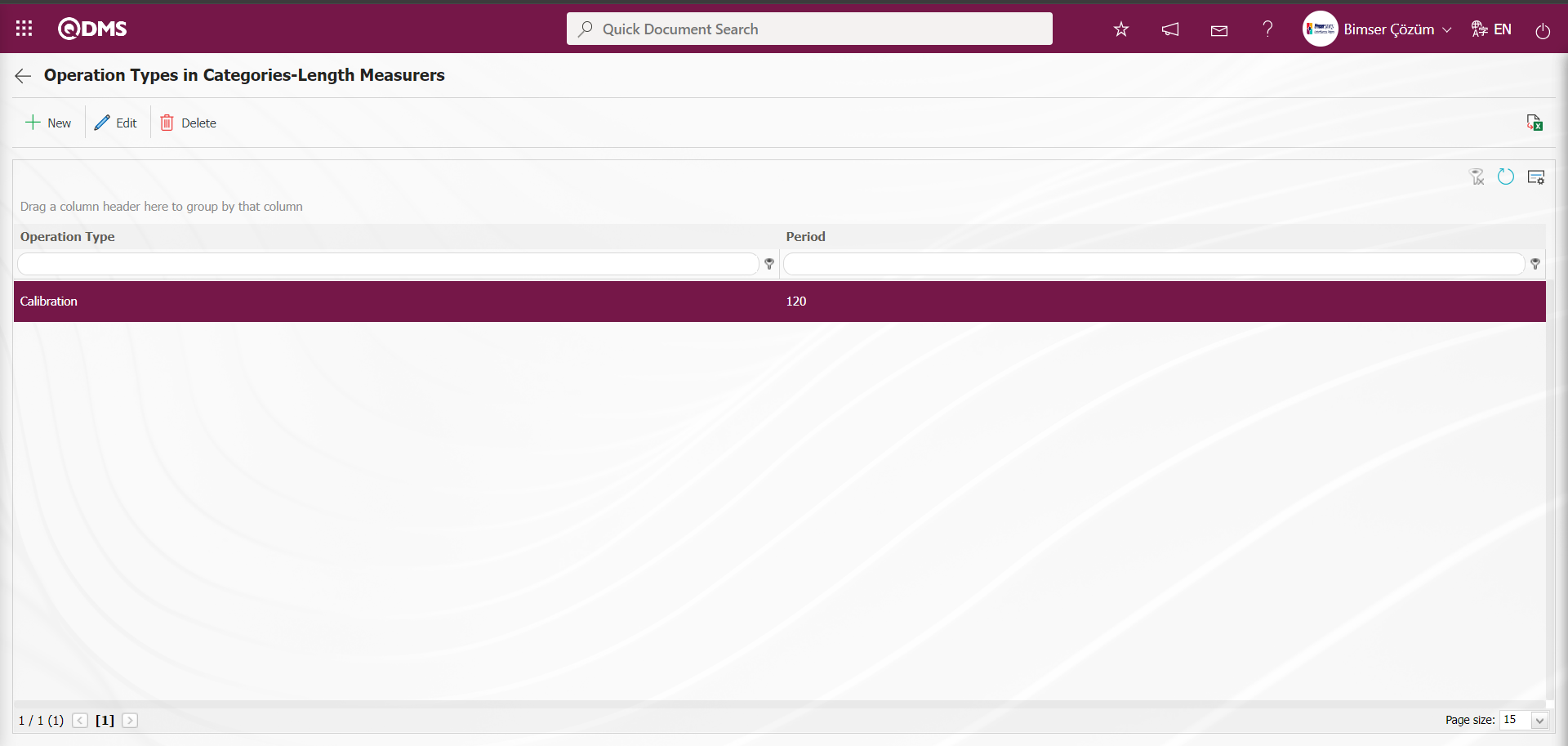
The operation type information of the operation types belonging to the category is selected from the list of operation types defined in the system. Enter the period information of the operation type belonging to the category. Enter the pre-notification period in days. Status section is selected as active. After the required fields are filled in, the  button in the upper left corner is clicked and the registration process of defining sub operation types for the category is realized.
6.1.2. Operation Location
Menu Name: System Infrastructure Definitions/ Device Management System/ Operation Location
It is the menu where the process of defining the places where the devices are processed outside the system is realized. The devices used in the company can be sent to accredited laboratories for calibration procedures.
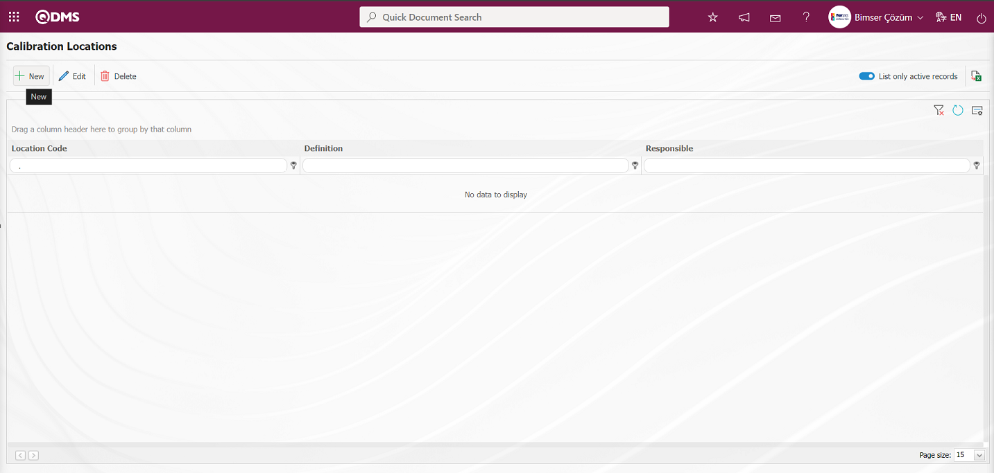
With the help of the buttons on the screen;
: Defining a new operation location is done.
: Changes and edits are made on the selected operation location information in the list.
: Delete the selected operation location information in the list.
 : When the check box related to the relevant field is checked, the records with active status are listed in the operation location list.
 : Operation location list is reported in Excel format.
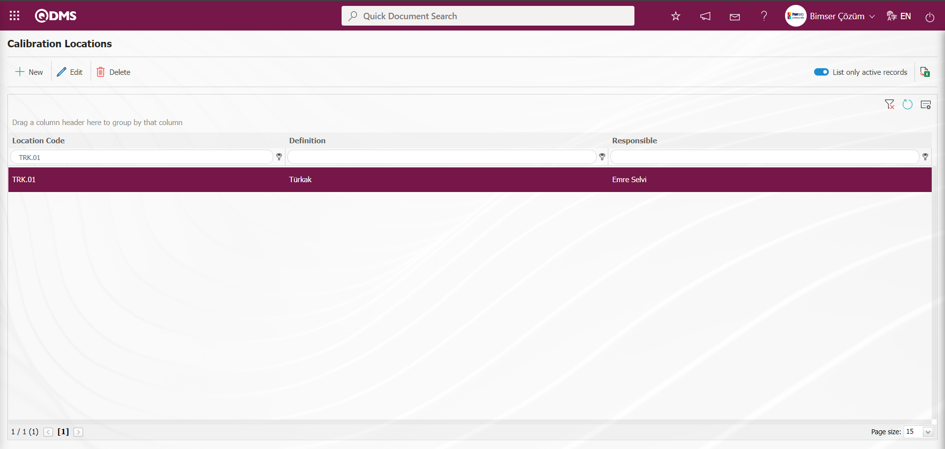
To add a new operation location to the list, click the button in the upper left corner of the screen and the Calibration Location Definition screen is displayed.
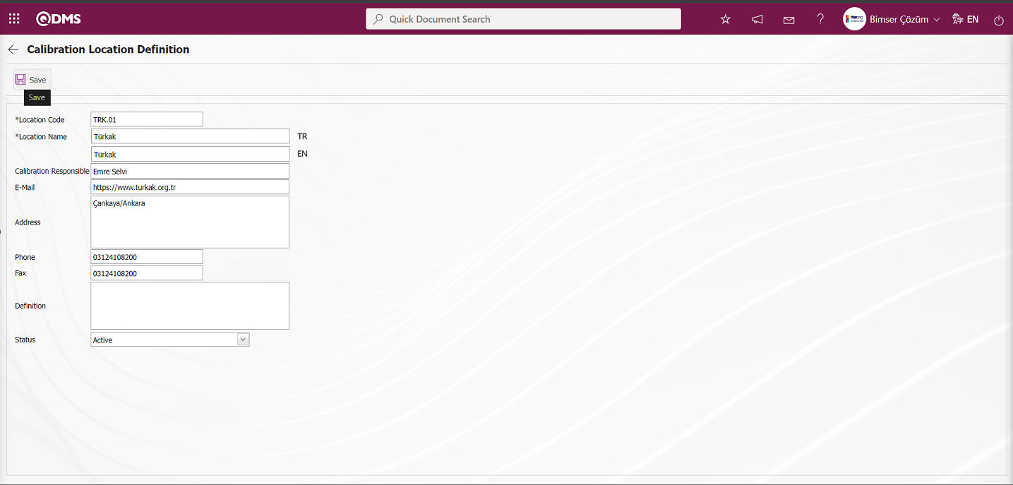
Related fields are defined on the screen that opens:
Location Code: This is the field where the code information of the process location defined in the Calibration Location Definition screen is written.
Location Name: This is the field where the name of the process location defined in the Calibration Location Definition screen is written.
Calibration Responsible: It is the field where the information of the process responsible of the process location defined in the Calibration Location Definition screen is written.
E-mail: It is the field where the e-mail information of the process location defined in the Calibration Location Definition screen is written.
Phone: It is the field where the phone information of the process location defined in the Calibration Location Definition screen is written.
Addres: It is the field where the address information of the trading location defined in the Calibration Location Definition screen is written.
Fax: This is the field where the fax information of the process location defined in the Calibration Location Definition screen is written.
Definition: It is the field where the details and description information of the process location defined in the Calibration Location Definition screen is written.
Status: It is the field where the passive or active status of the process location defined in the Calibration Location Definition screen is selected.
The status section is selected active by entering information such as code, name, responsible person, e-mail and address. After the required fields are filled in, the  button in the upper left corner is clicked and the process location definition registration process is realized.
The locations saved in the process location definition section will be valid for devices that are processed outside. If the device is calibrated or verified inside, you can select the place where the device is processed from the System Infrastructure Definitions / BSID / Definitions / Company Profile Definition menu and the operations to select the location of the device are performed in this menu. The process of determining where the device is located in the company can be performed. To calibrate or verify the device inside, the System Infrastructure Definitions / BSID / Definitions / Company Profile Definition menu is clicked. 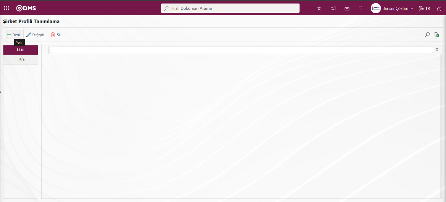
With the help of the buttons on the screen;
: Defining a new company profile
: Changes and edits are made on the company profile information selected in the list.
: Delete the company profile information selected in the list.
: When the check box related to the relevant field is checked, the records with active status are listed in the company profile list.
: Reporting of the company profile list in Excel format is done.
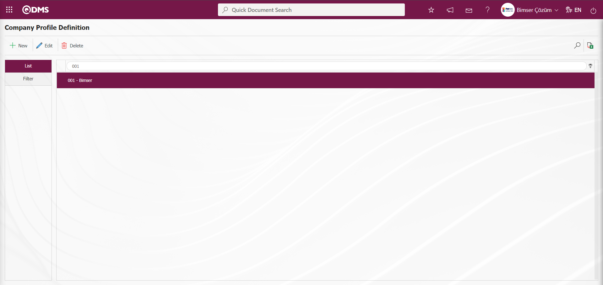
To add a new company profile to the list, click on the button in the upper left corner of the screen and the Company Profile Definition - New Record screen is displayed.
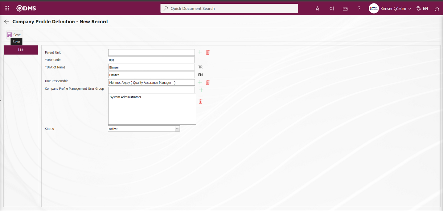
Related fields are defined on the screen that opens;
Parent Unit: Company Profile Definition - New Record screen If you want to define a new Company Profile that is connected to a Company Profile under a Company Profile defined in the system, if you want to create a sub-division, click the  (Select) button and select the Company Profile from the Company Profile list defined in the system.**
Unit Code: This is the field where the code information of the company profile defined on the Company Profile Definition - New Record screen is defined. It should be defined without using characters such as spaces and Turkish characters, so that it is not the same as the previously defined fields. Ex. '001' , 'RK'
Unit of Name: This is the mandatory field where Company Profile Definition - New Record screen Company Profile definition information is defined.**
Unit Responsible: Company Profile Definition - New Record screen  (Select) is the field where the responsible person of the company profile is selected from the list of personnel defined in the system opened by clicking the button.**
Company Profile Management User Group: Company Profile Definition - New Record screen Company Profile Management User Group (Add) is the field selected in the User Group list opened by clicking the button.
Status: Company Profile Definition - New Record screen This is the field where the “Active” option is selected in the “Active” and “Inactive” options of the status information. Inactive status is a sign that the Company Profile information is no longer used in the system. In order to see unused Company Profile information, it is necessary to search by selecting the “Passive” option in the status field in the search criteria from the filter tab.
In Company Profile Definition - New Record screen, if there is a supercode information in company profile definition, it is selected from the Company Profile list registered in the system. Unit code and unit name definition is written. Unit responsible is selected from the list of Personnel defined in the system Company Profile Management User Group is selected from the list of User Group defined in the system. Status information “Active” is selected. After the required fields are filled in, the Company Profile Definition registration process is realized by clicking the  button in the upper left corner.
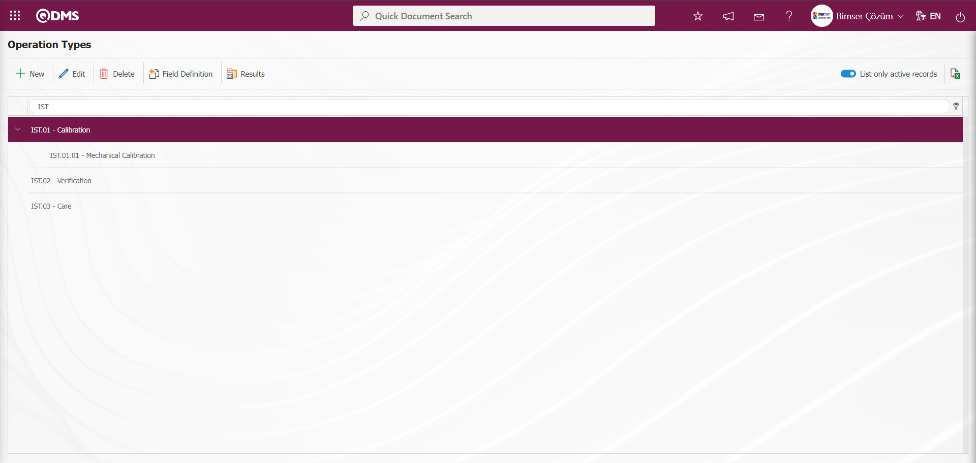
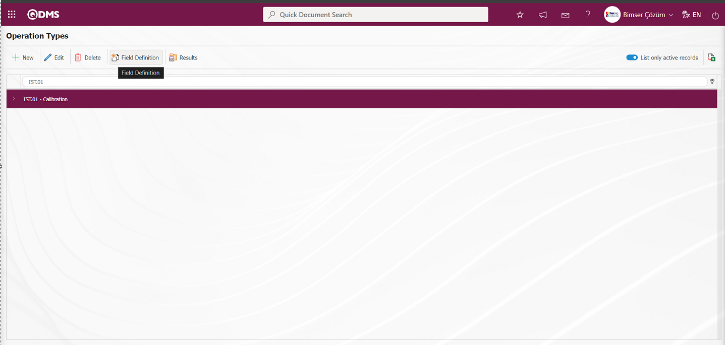
6.1.3. Operation Type Definition
Menu Name: System Infrastructure Definitions/ Device Management System/ Operation Type Definition
This is the menu where all operation types within the scope of the Device Management Module are defined. In this menu, calibration, verification and maintenance operation types are defined. While calibration is performed by an authorized company outside the company by defining a processing location, verification is performed by defining a company profile within the company itself. Calibration, verification and maintenance are generally used operation types.

With the help of the buttons on the screen;
 : Defining a new operation type is done.
: Edit and update the selected transaction type information in the list
: Delete the selected operation type information in the list.
 : The process of defining custom fields for the operation type information selected in the list is performed. In the Field Definition screen, the definition process of parametric field types such as Text, Multiple Text, Number and Date selected in the Data Type field is performed. These defined operation type custom fields are displayed in the operations tab on the operation report screen of the device to which the operation type is applied.
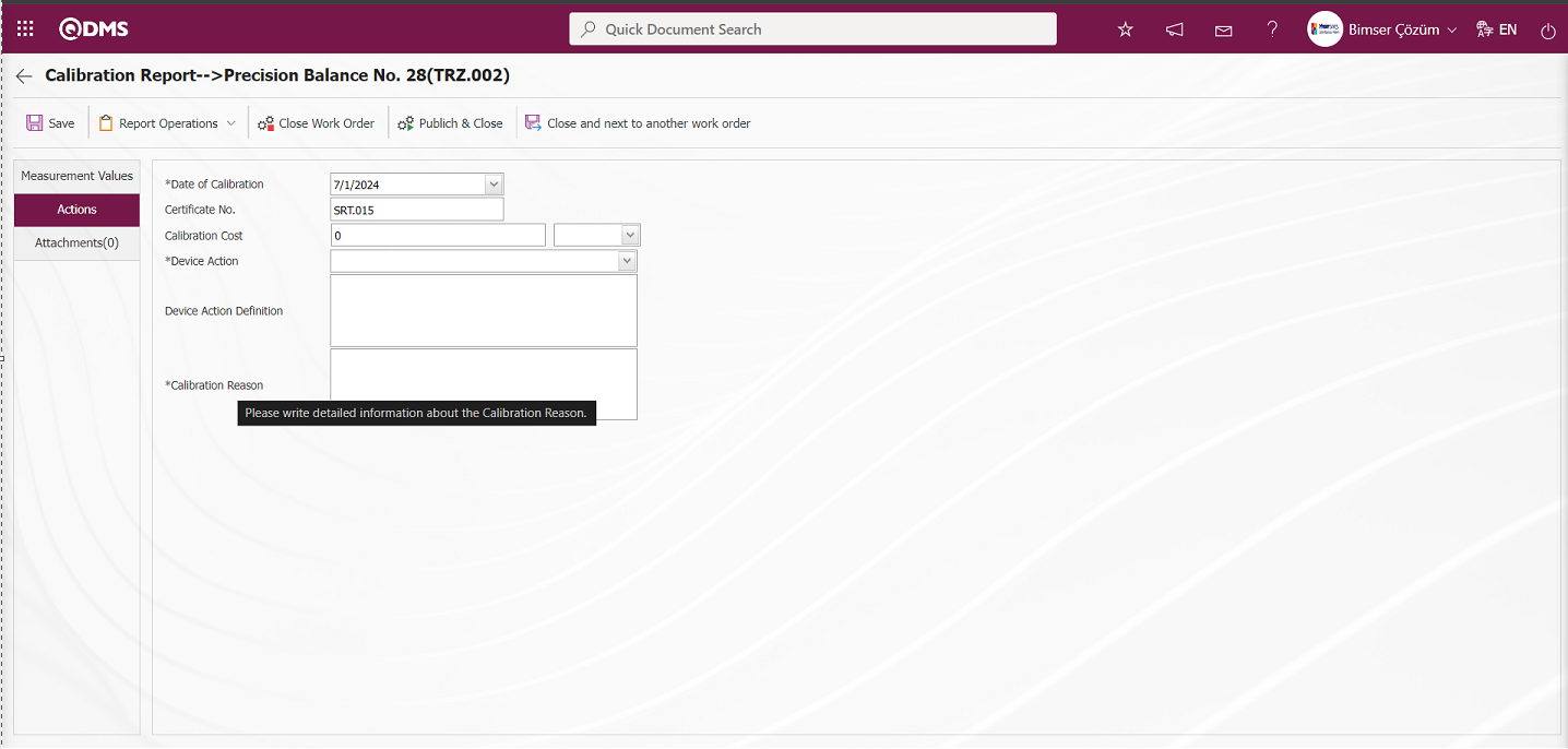
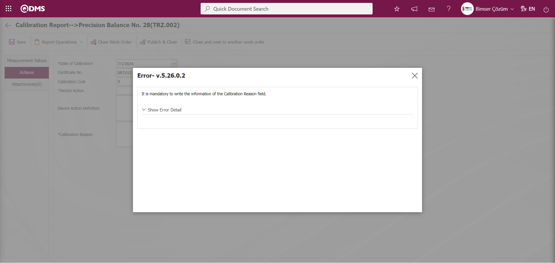
 : Defining the results related to the operation type information selected in the list. Defining the results that occur as a result of the operation type applied to the device. For example: Not suitable for use, Out of use / to be scrapped and Continued use. These defined results are presented as options in the Operation for the Device field in the Operations tab on the operation report screen of the device to which the operation type is applied. The calibration report of the device is prepared by selecting from these options. If no selection is made in this field, the system gives an error message when the calibration report is received.
 : When the check box related to the relevant field is checked, the records with active status are listed in the Operation Type list.
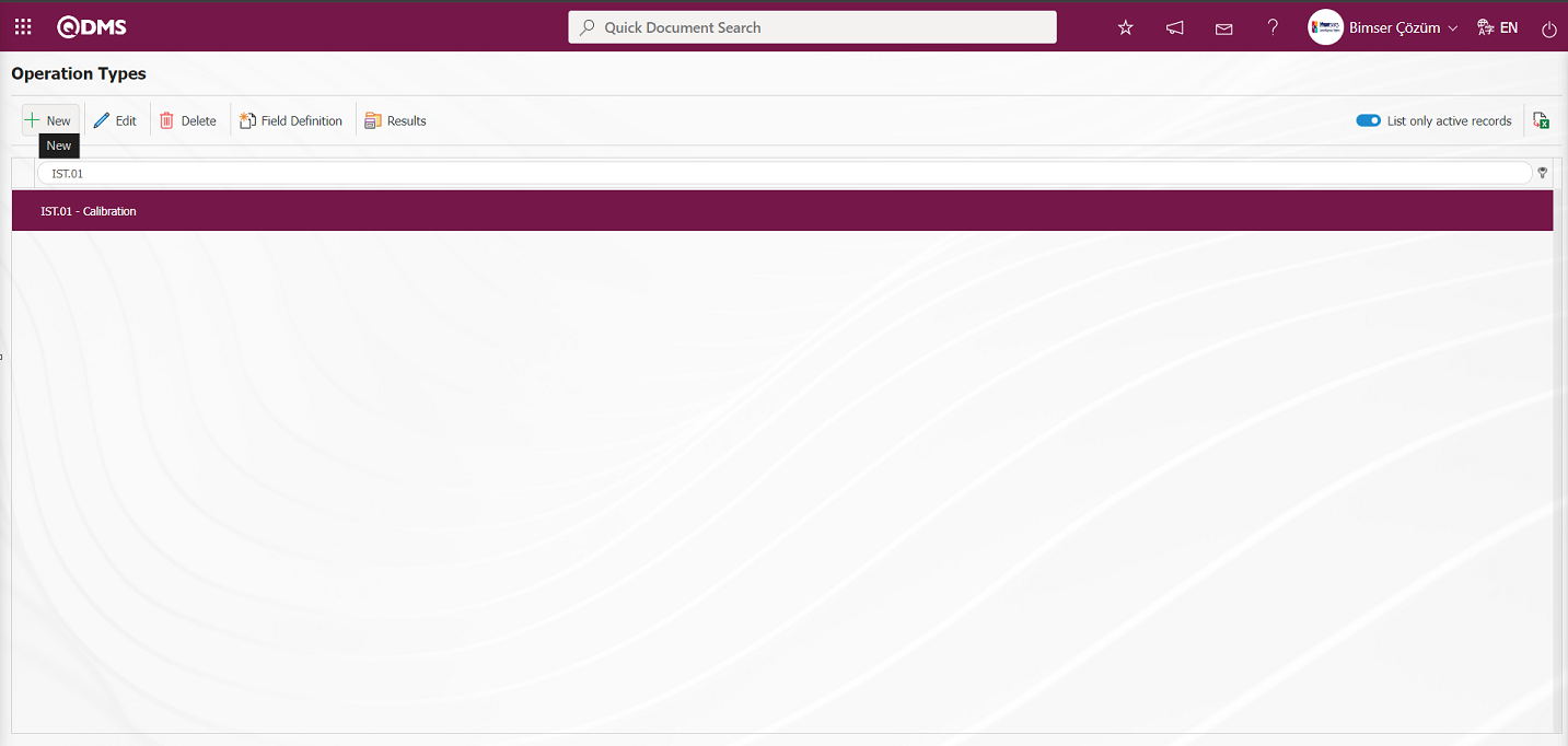
: The process of obtaining the report of the Operation Type list in Excel format is done.
To add a new operation type to the list, click on the button at the top left corner of the screen and the Operation Type Definition screen is displayed.
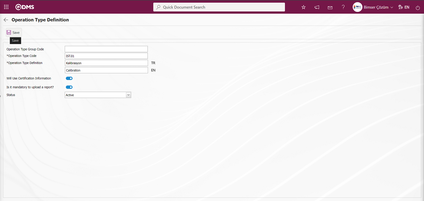
Related fields are defined on the screen that opens:
Operation Type Group Code: This is the field where the operation type group code information defined from the Operation Type Definition screen is selected from the list of operation types defined from the system.
Operation Type Code: This is the field where the operation type code information defined from the Operation Type Definition screen is written. It should be defined without using characters such as spaces and Turkish characters so that it is not the same as the previously defined code information. For example. '001', 'RK'.
Operation Type Definition: This is the field where the operation type definition information defined from the Operation Type Definition screen is written. The English language equivalent of the definition part of the operation type is written in the field with the English language equivalent icon.
Will Use Certification Information: If the operation type defined on the Operation Type Definition screen will use the certificate information, the check box will be checked. Opens the option to add certificates according to the operation type.
Is it mandatory to upload a report?: When this transaction type defined in the Operation Type Definition screen is selected, the relevant check box is checked if it is required to upload a report.
Status: Passive or active status information can be selected on the Operation Type Definition screen. Status information is divided into two as “active” and “passive”. The operation type defined as active refers to the operation type used in the system. If a transaction type definition will no longer be used in the system, the status information should be changed to “passive”. Thus, both the existing records in the past are not affected and the inactive transaction type information is not displayed on the new Transaction Type selection screens.
Enter the operation type code and definition information on the screen that opens. The status section of the operation type is selected as active. After the required fields are filled in, the operation type definition registration process is realized by clicking the  button in the upper left corner of the screen.
Operation to define a transaction type based on the operation type sub-division: If the operation type is to be created for the first time, the operation type group code box is empty, but if a transaction type is selected from the list and the new operation type creation screen is accessed, the code of the selected operation type comes as a group code. Sub-divided transaction type definition is made depending on the transaction type with group code.
To define a sub-division operation type in the Operation Types menu, click the  button while the operation type is selected in the list.
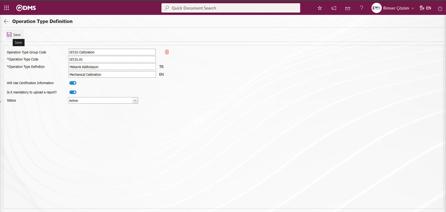
After the required fields are filled in, the Operation Type Definition registration process is performed by clicking the  button in the upper left corner of the screen. The process of defining the operation type of the sub-breakdown operation type connected to the operation type is performed.
In the Operation Type Definition menu, all operation types are defined by performing the same process steps in this way.
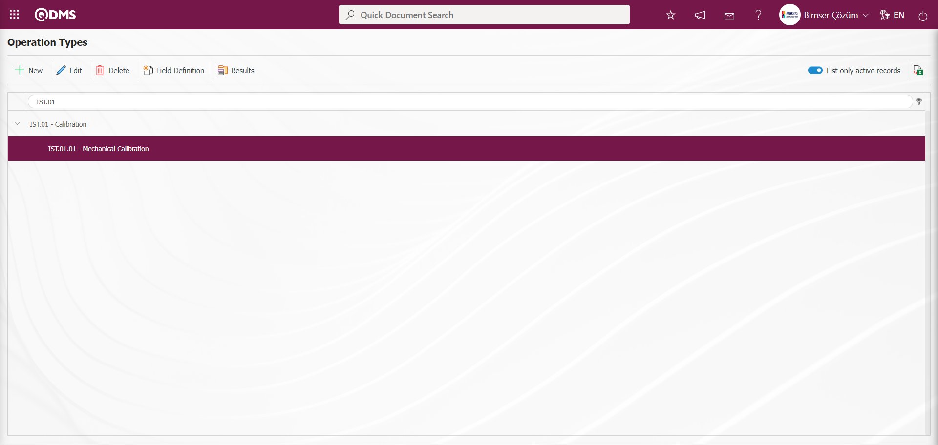
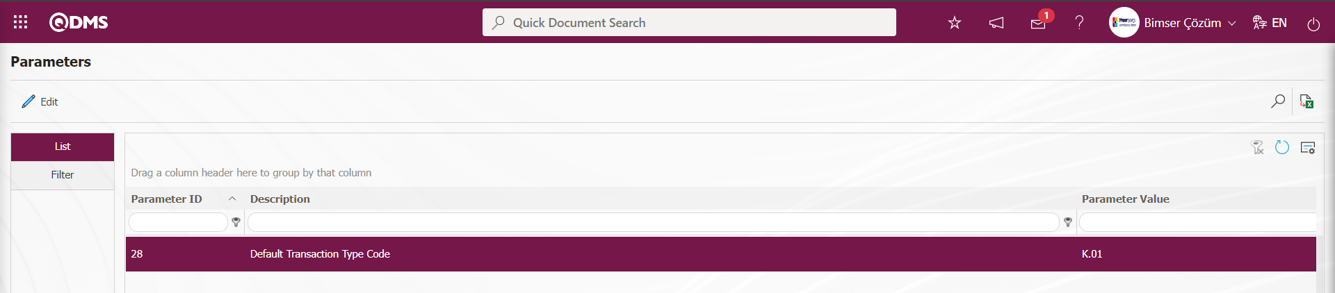
According to the transaction type code defined in the parameter value of parameter 28 in the Device Management System parameters, the transaction type is automatically brought by the system in the filter tab on the Device Definition screen.
Operation Type Specific Parametric Type Field Definition Process: If  button is clicked while a operation type is selected in the list, only parametric fields specific to that operation type can be defined. These special fields can also be added to the calibration report. In the Field Definition screen, text, text multiple, date and list type parametric fields can be defined.
To define a parametric field specific to the Operation Type, click on the button while the Operation Type is selected in the list on the Operation Types screen.
The Field Definition screen opens.

With the help of the buttons on the screen;
: Defining a new field is done.
: Changes and updates are made on the field information selected in the list.
: Delete the selected field information in the list
 : If the defined field is a list type parametric field, list elements are defined.
 : Return to the previous screen.
To add a new parametric field type to the list, click the button on the upper left corner of the screen to display the Field Definition screen.
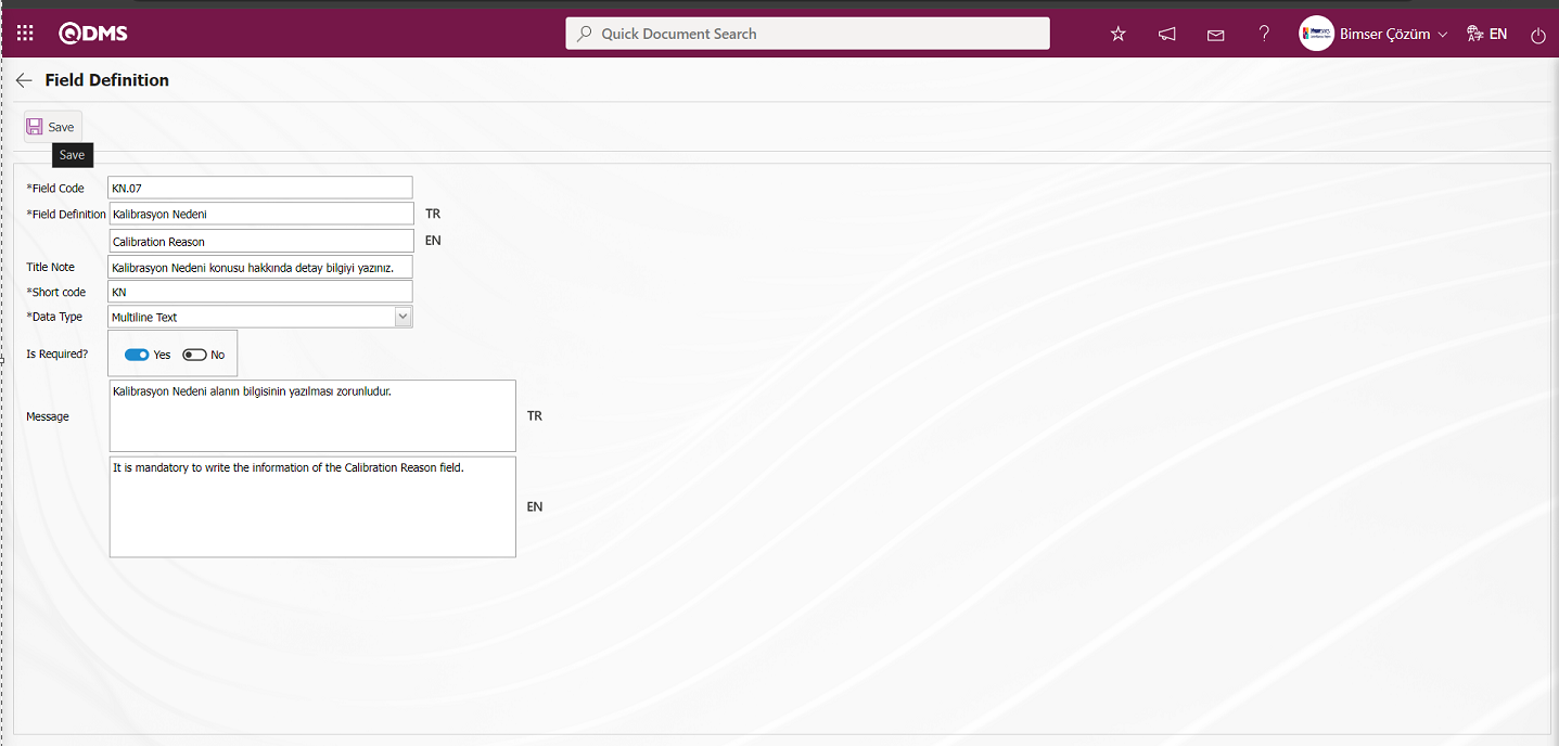
Related fields are defined on the screen that opens:
Field Code: This is the field where the code information of the field defined in the Field Definition screen is written. It should be defined without using characters such as spaces and Turkish characters so that the previously defined code information is not the same. For example. '001' , 'RK'.
Field Definition: This is the field where the definition information of the field defined in the Field Definition screen is written. In the field with the English language equivalent icon, the English language equivalent of the definition part of the parametric field type is written.
Title Note: This is the field where the title note information of the field defined in the Field Definition screen is written. It is the descriptive information about the field displayed when the mouse hovers over the field.
Short Code: This is the field where the short code information of the field defined in the Field Definition screen is written.
Data Type: It is the field where the parametric field type defined in the Field Definition screen is selected. The selection is made in data type options such as Text, Multiple Text, Numeric, Personnel, Date, List. Ex: The defined parametric field type is selected as Multiple Text.
Is Required?: This is the field where the “Yes” option is selected in the “Yes” and “No” options for entering data as a mandatory field for the parametric field type defined on the Field Definition screen. When the field is not required to be a mandatory field, it is considered appropriate to select the “No” option.
Message: This is the field where the system writes the mandatory warning message to be given by the system when the parametric field type defined in the Field Definition screen is selected as a mandatory field. In the field where the English language equivalent icon is located, the English language equivalent of the mandatory warning message of the parametric field type is written.
In the screen that opens, Field Code, Field Definition and Short Code information are entered, Data Type is selected and  button is clicked to define a multi-text type parametric field specific to the transaction type. The short code information here is the abbreviation that will be used to reflect the information written in the field or selected in the field to the Calibration report. According to the selection made in the data type field, text, date, personnel, position, department and list type parametric fields can be created.
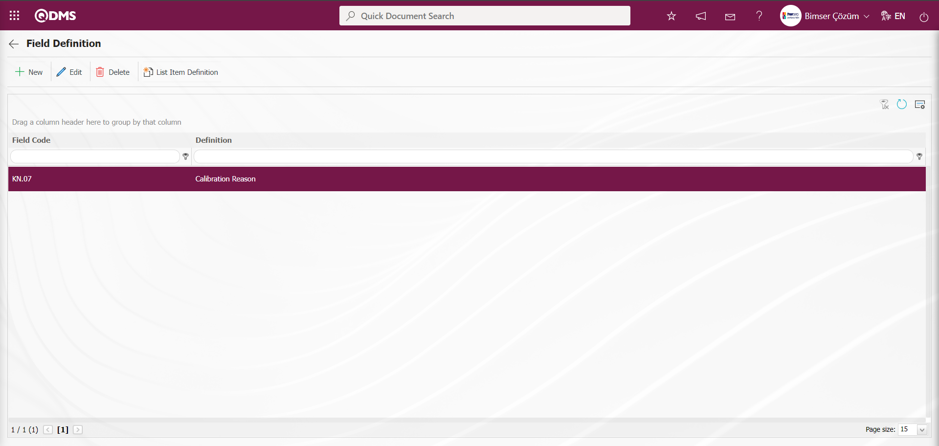
The defined multi-text type field is displayed on the Calibration Report screen. When the mouse hovers over it, the defined title note information is displayed.
When data entry is not made in the multi-text type field defined when the registration is made on the Calibration Report screen, a warning message about the necessity of the field is given by the system.
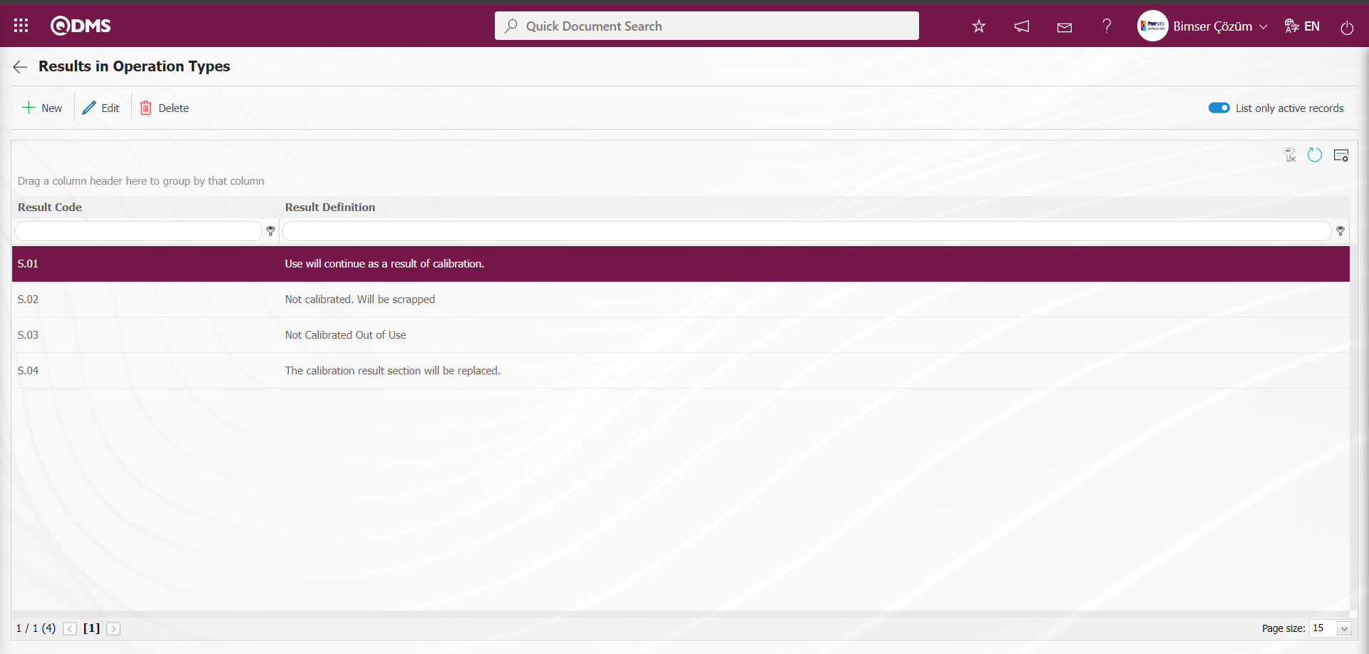
Defining the Result Depending on the Operation Type: If the  button is clicked while any of the operation types is selected, the situations that will occur as a result of that operation type are defined. Examples of these situations are; “Calibration result will continue to be used”, “Not calibrated. It will be scrapped.”, ”Not calibrated. The department will change.”, ”Not calibrated. Out of Use”, ‘Calibration result section will be changed’. These results will also be used when creating a calibration report. On the Calibration Report screen, the result of the operation applied to the device is selected by displaying it in the “Device Action” field.
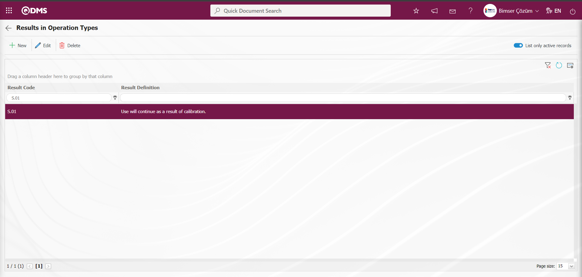
For defining the result depending on the operation type, the button is clicked while the operation type is selected in the list.
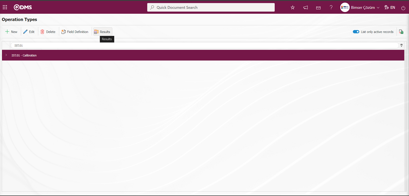
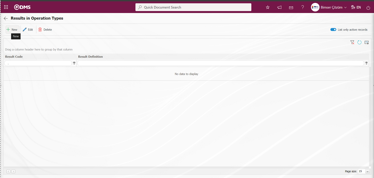
The Results in Operation Types screen opens.
With the help of the buttons on the screen;
: Defining the result of a new operation type is done.
 : Changes and updates are made on the result information of the selected operation type in the list.
 : Delete the result information of the selected operation type in the list.
 : Returns to the previous screen.
 :When the check box related to the relevant field is checked, the records with active status are listed in the result list.
: The search criteria on the menu screens are used to clean the data remaining in the filter fields in the grid where the search operation is performed.
: The menu screen is restored to its default settings.
: User-based designing is done on the menu screen with the show-hide feature, that is, the hiding feature of the fields corresponding to the columns on the menu screens.
To add a result of a new transaction type to the list, the Result Definition screen is displayed by clicking the button in the upper left corner of the screen.
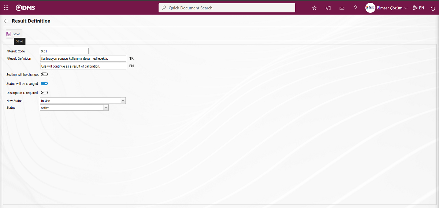
Related fields are defined on the screen that opens:
Result Code: This is the field where the code of the result defined in the Result Definition screen is written. It should be defined without using characters such as spaces and Turkish characters so that the previously defined code information is not the same. For example. '001' , 'RK'.
Result Definition: This is the field where the definition information of the result defined on the Result Definition screen is written.
Section will be changed:If the section of the result defined on the Result Definition screen is to be changed, the relevant check box is checked. If the section to be changed is activated, the new section of the device is selected in the relevant field.
Status will be changed: If the status of the result defined in the Result Definition screen will be changed, the related check box is checked. If the status of the device will be changed is activated, the status information is selected in the new status field.
Description is Required: If the description information of the result defined on the Result Definition screen is required to be mandatory, the check box related to the relevant field is checked.
New Status: It is the field where the new status is selected from the status options such as scrap, in use, defective, which are defined without defining the predefined status of the result defined on the Result Definition screen.
Status: It is the field where the passive or active status of the result defined on the Result Definition screen is selected.
On the screen that opens, enter the result code and result definition information and select the active status. The check box related to the Status to be changed field is checked. The new status of the device is selected in the New Status field. After the required fields are filled in, the result definition registration process is performed by clicking the  button in the upper left corner of the screen.
On the Results in Operation Types screen, the same steps are used to define all the results of the operation type.
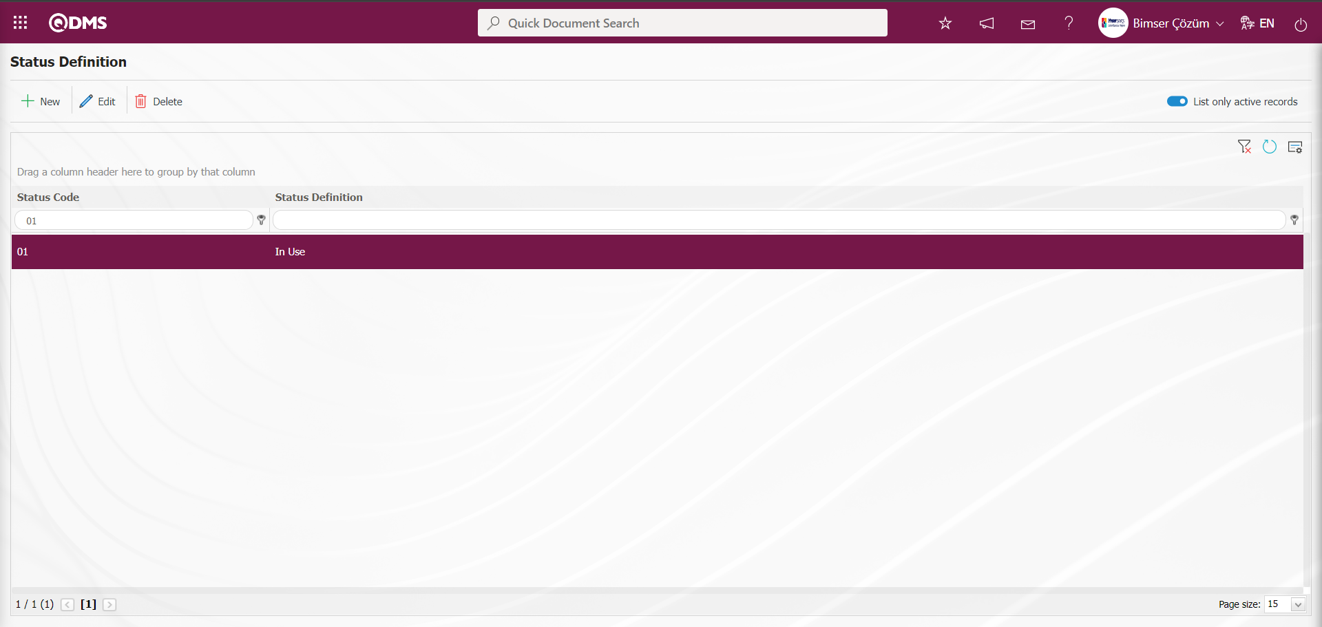
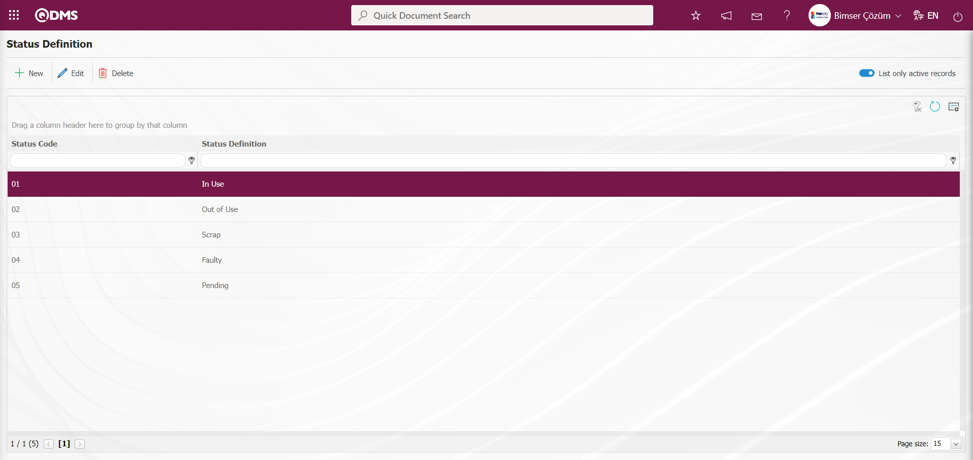
6.1.4. Status Definition
Menu Name: System Infrastructure Definitions/ Device Management System/ Status Definition
This is the menu where the status information of the device is defined. When the check box related to the “Status will be changed” field is checked while defining the transaction type results, the status of the device such as scrap, in use, defective, pending and out of use, which should be selected in the new status field, is defined in this menu. The status information of the device is expressed in this menu.
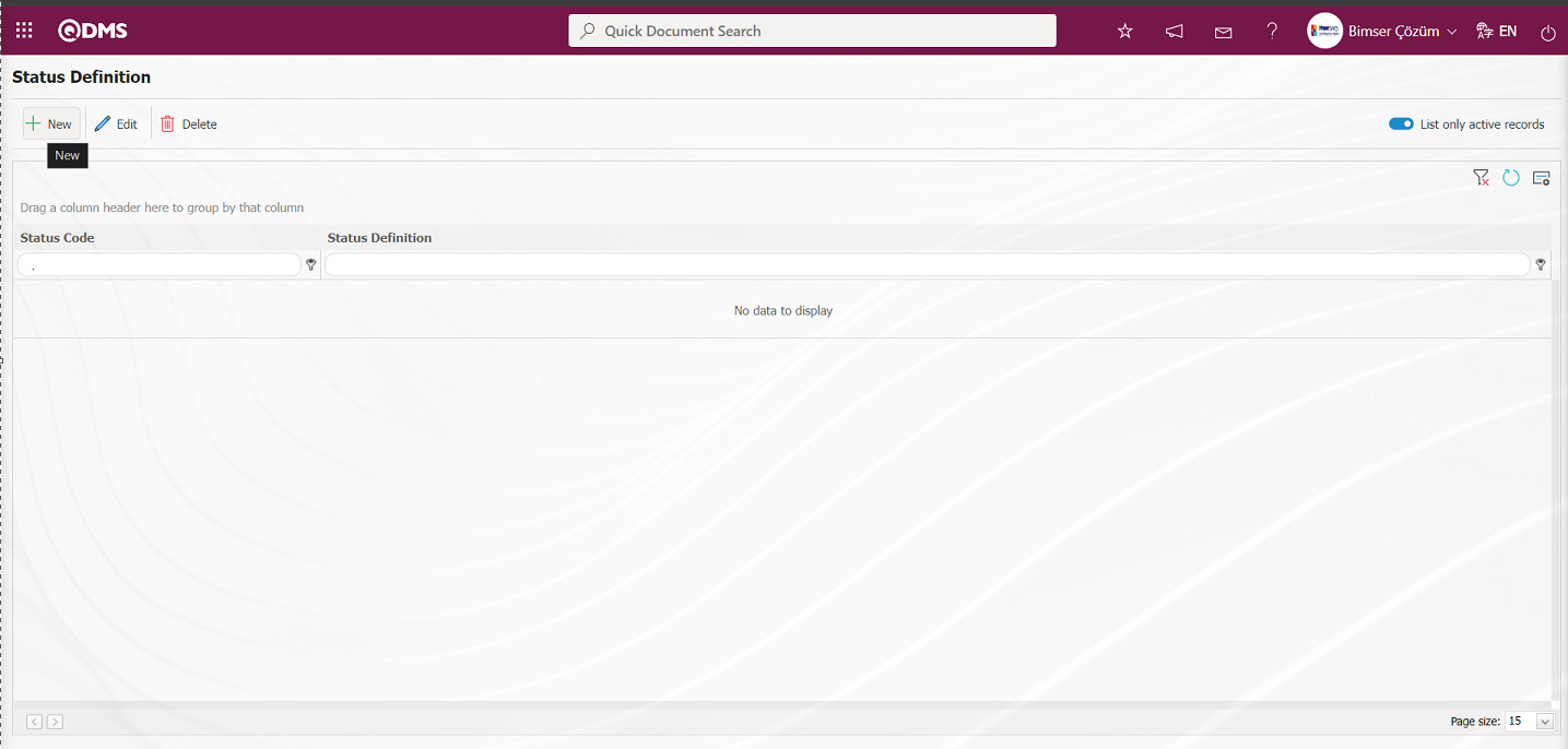
With the help of the buttons on the screen;
: Defining a new status is done.
: Changes and updates are made on the status information selected in the list.
 : When the check box related to the relevant field is checked, it is ensured that the records with active status are listed in the Status list.
: The search criteria on the menu screens are used to clean the data remaining in the filter fields in the grid where the search operation is performed.
: The menu screen is restored to its default settings.
: User-based designing is done on the menu screen with the show-hide feature, that is, the hiding feature of the fields corresponding to the columns on the menu screens.
To add a new Status to the list, the Status Definition screen is displayed by clicking the button in the upper left corner of the screen.
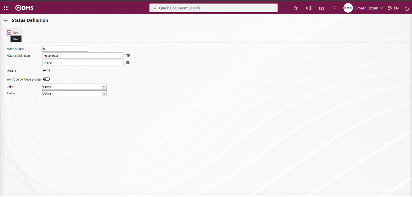
Related fields are defined on the screen that opens:
Status Code: This is the field where the code information of the status defined in the Status Definition screen is written. It should be defined without using characters such as spaces and Turkish characters so that the previously defined code information is not the same. For example. '001' , 'RK'.
Status Definition: This is the field where the definition information of the status defined in the Status Definition screen is written. In the field where the English language equivalent icon is located, the English language equivalent of the definition part of the defined status is written.
Default:If the default information of the status defined on the Status Definition screen is to be selected, the relevant check box is checked. In the selected fields related to the status field, the status marked in the check box related to the default is automatically defaulted by the system.
Won't be continue process : This is the field where the check box is checked if the status defined in the Status Definition screen will be selected as Won't be continue process. Won't be continue process If the check box is selected, calibration etc. operations will not continue, it will be out of use.
Color: This is the field where the status defined on the Status Definition screen can be selected from the color options. In the Device List screen opened in the Device Identification menu, coloring is done according to the status of these devices made in the list tab. For example: In the device list, devices whose status is in use are displayed in green, scrap devices in red and defective devices in brown.
Status: This is the field where the passive or active status of the status defined in the Status Definition screen is selected.
On the screen that opens, the status code and definition information is entered. The color of the status is selected from the relevant options. The status part of the status is selected active. After the required fields are filled in, the status definition registration process is realized by clicking the  button in the upper left corner of the screen.
In the Status Definition screen, the same process steps are used to define all the statuses related to the device. When the Scrap status is defined in the Status Definition screen, the check box related to the “Won't be continue process ” field is checked.
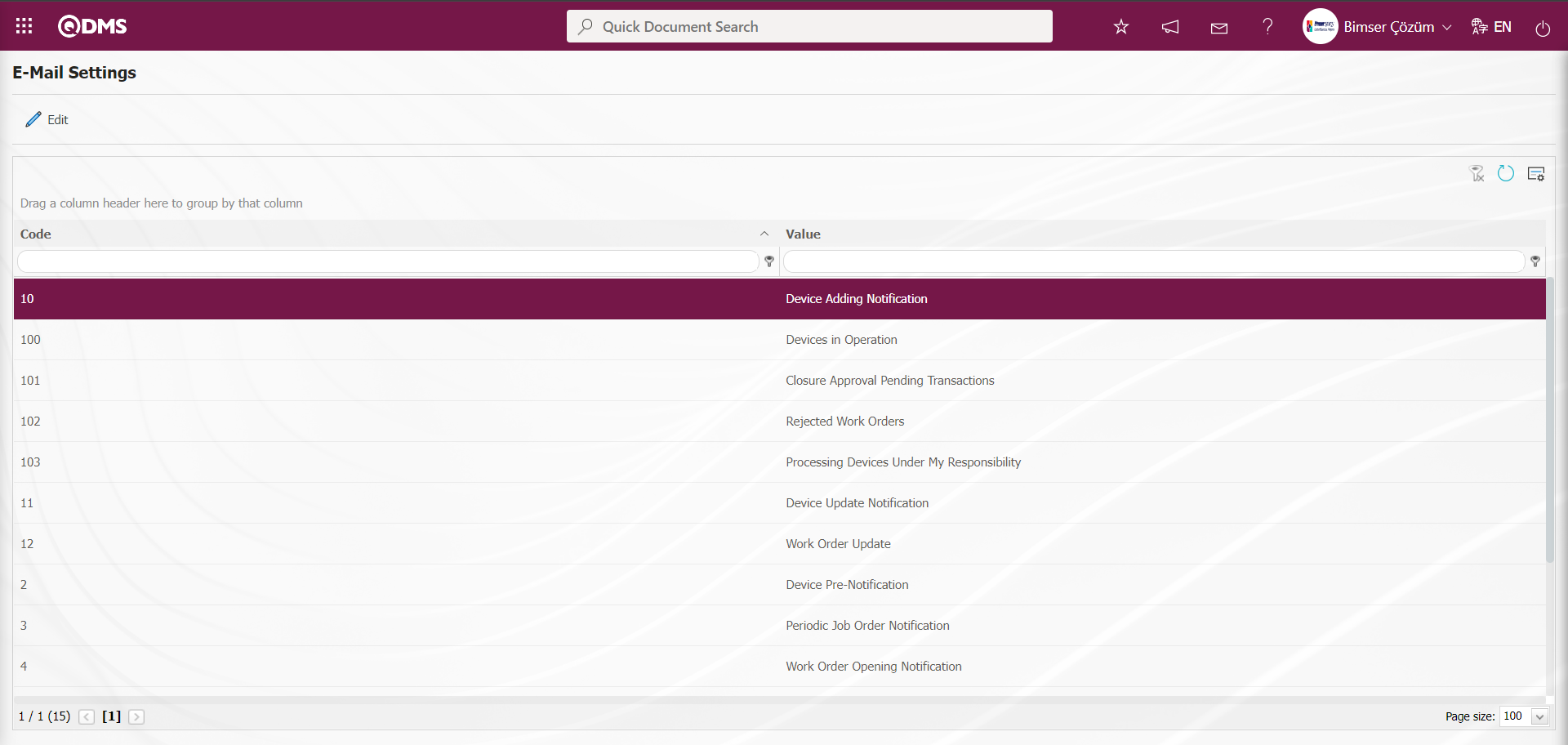
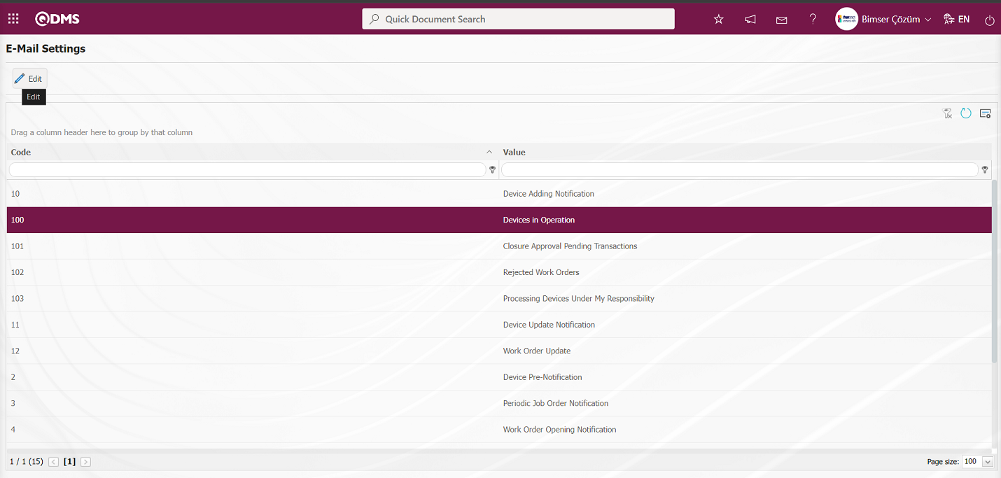
6.1.5. E-Mail Settings
Menu Name: System Infrastructure Definitions / Device Management System / E-Mail Settings
It is the menu where e-mail notifications are made within the scope of the Device Management System Module. In the E-Mail Settings screen, it is determined at which stage of the “Device Management System” module to whom e-mails will be sent.
With the help of the buttons on the screen;
 : Editing/changing/updating is done on the value of the e-mails selected in the list.
: Clearing the data remaining in the filter fields in the grid where the search criteria search operation on the menu screens is performed
: The process of returning the menu screen to its default settings is done.
: User-based designing of the menu screen is done with the show-hide feature, that is, the hiding feature of the fields corresponding to the columns on the menu screens.
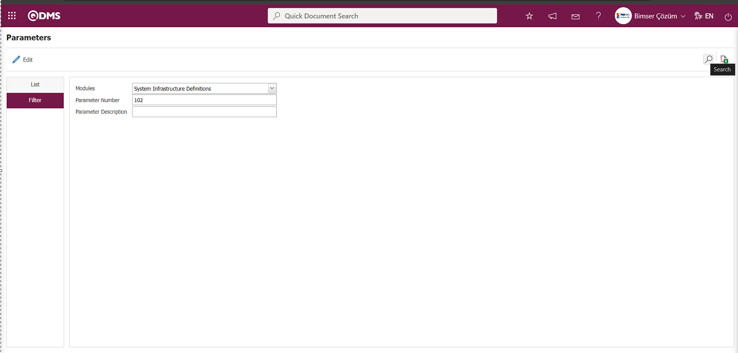
If SMS notification will be used in E-mail Settings;
Click on System Infrastructure Definitions/BSID/Configuration Settings/ Parameters menu. In the parameters of the System Infrastructure Definitions module parameters listed on the Parameters screen, the parameter number 102 “Will using SMS notification?” is selected by typing the parameter number in the parameter no field in the Filter tab on the parameters screen and clicking the  (Search) button.
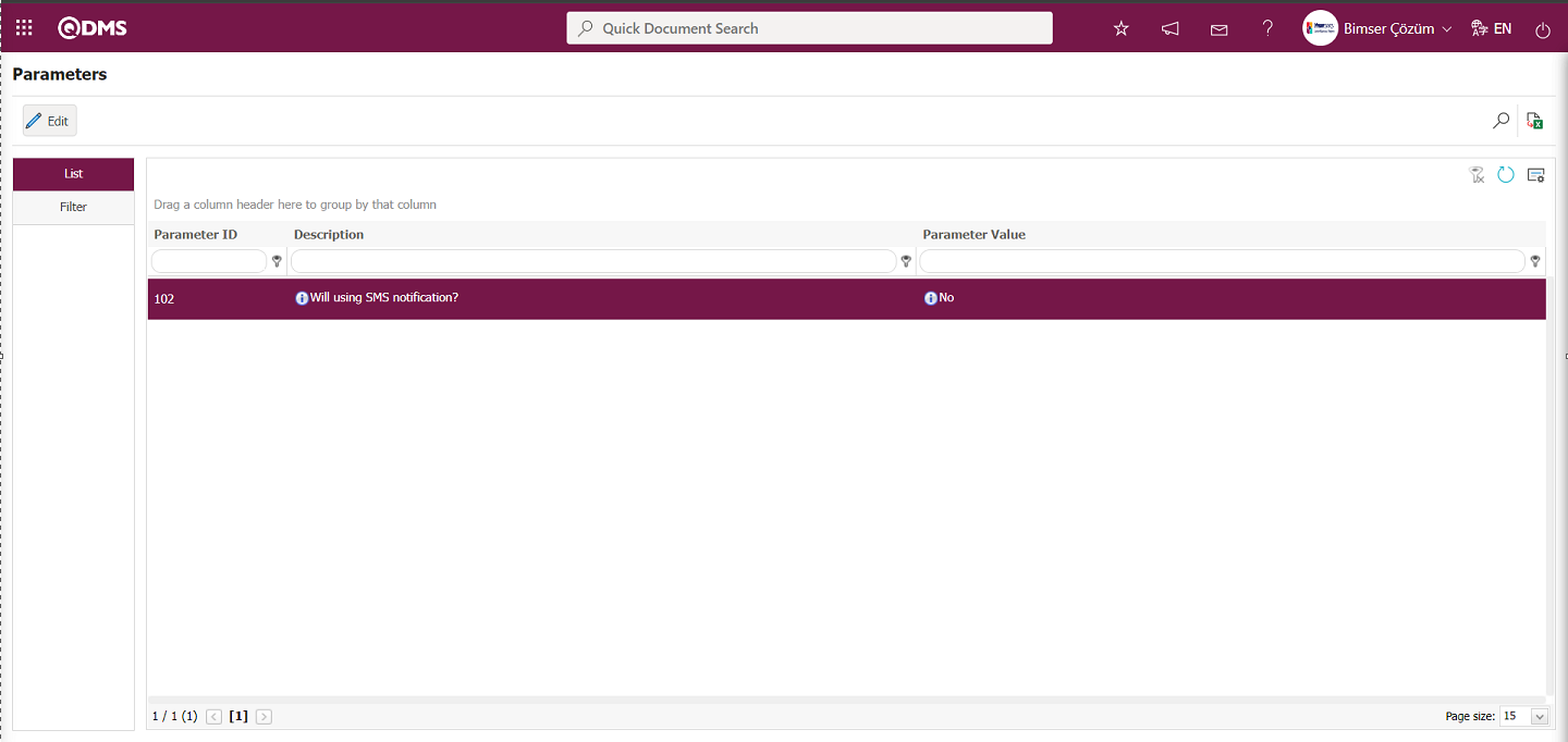
After selecting parameter 102 “Will using SMS notification? ” in System Infrastructure Definitions module parameters, click  button.
Select the parameter value ‘Yes’ on the parameters screen.
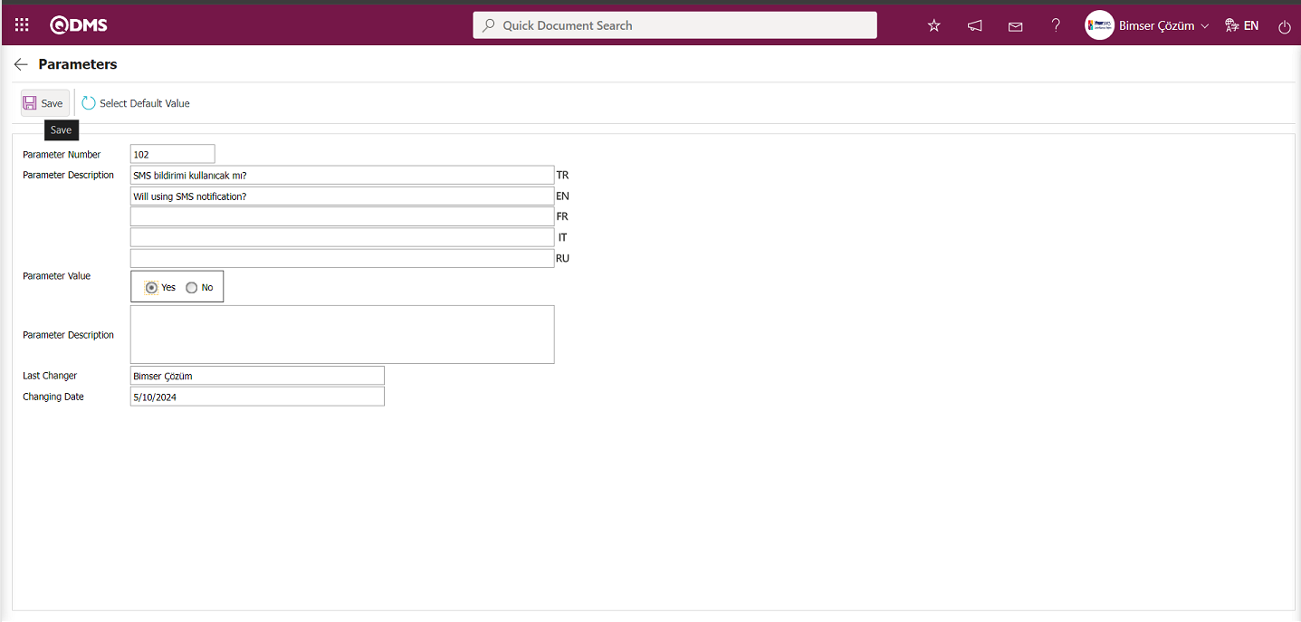
After selecting the parameter value ‘Yes’ on the Parameters screen, the  button on the top left of the screen is clicked and the parameter is activated.

After the parameter is activated, the check box related to the “Send SMS” field related to the use of SMS notification is displayed on the E-Mail Settings screen. By checking the relevant check box, SMS notification is used in E-Mail settings.
Select which step you want to send e-mail/message and click the  button.
For example: On the E-Mail Settings screen, select the “Devices in Operation” step and click the  button.
 The E-Mail Settings/ Devices in Operation screen is displayed. The Roles section shows the role to which my e-mail and message notification will go.
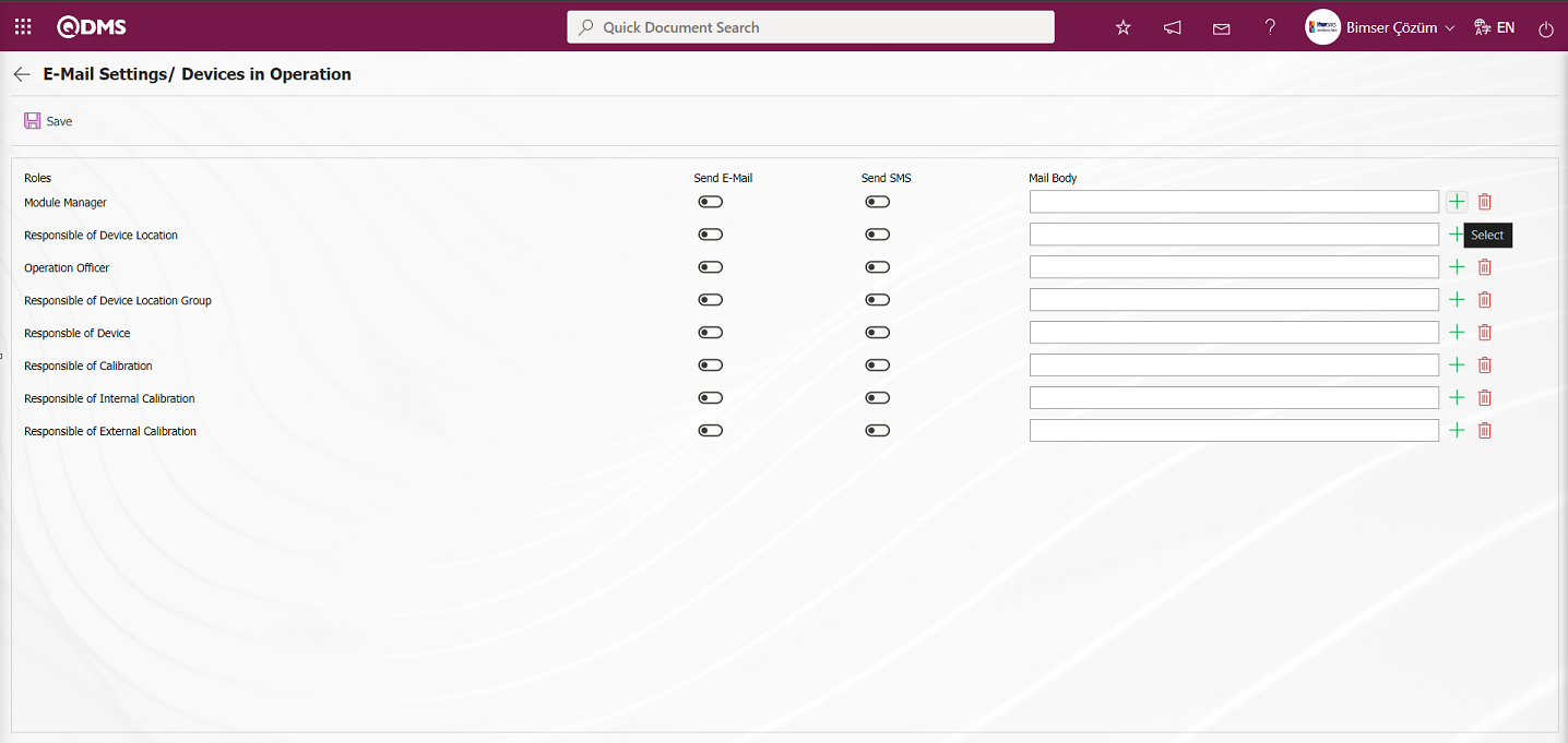
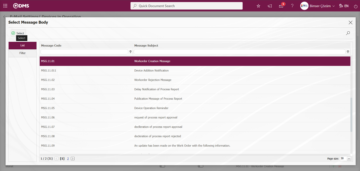
On the E-Mail Settings/ Devices in Operation screen, click the  (Select) button and select the message body to be sent from the relevant list in the Message Body list defined in the system. The
  (Delete) button is used to delete an incorrectly added message body.
The message bodies to be sent for the relevant roles are selected by selecting the message body in the message body list and clicking the  button.
If you want to send an e-mail to whom, the “Send E-Mail / Send SMS” check box related to that role is checked. The mobile phone number of the person defined in the role must be defined on the personnel identification screen in order to send a message
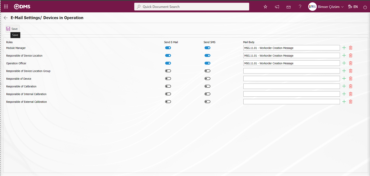
On the E-Mail Settings/ Devices in Operation screen, after the “Send E-Mail / Send SMS” check box related to the roles to send e-mail is checked, the E-Mail Settings registration process is performed by clicking the  button in the upper left corner of the screen.
6.1.6. Device Code Replacement
Menu Name: System Infrastructure Definitions / Device Management System/ Device Code Replacement
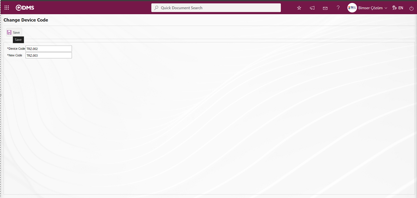
In the Device Code Change screen, the code of the device defined in the system is written in the Device Code field and the new code information to be changed is written in the New Code field. The code information to be written in the Device Code field is taken from the Integrated Management System/Device Management System/Device Identification menu. On the Change Device Code screen, the device code is changed by clicking the button in the upper left corner of the screen.
Related fields are defined on the screen that opens:
Device Code: This is the field where the old device code information is written on the Device Code Change screen. It is taken from the code information of the devices defined in the system in the Integrated Management System/Device Management System/Device Definition menu.
New Code: This is the field where the new device code information is written on the Device Code Change screen. The code information written in the New Code field must not be in the code information previously defined in the system.
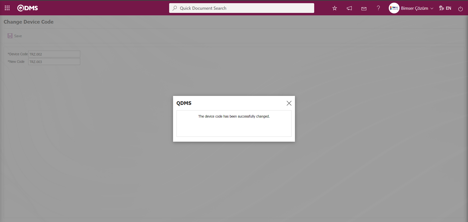
In the Change Device Code screen, the old code and new code information of the device is entered. After the required fields are filled in, the device code change registration process is performed by clicking the button in the upper left corner of the screen. After the Device Code Change registration process, the system will give the message “The device code has been successfully changed.” indicating that the device code change process has been realized.
6.1.7. Device Maintenance
Menu Name: System Infrastructure Definitions/ Device Management System/ Device Maintenance
It is the menu where the process of changing certain information of the devices collectively is performed. With the fields displayed in this menu, the information of all devices can be easily changed when desired. Depending on the fields displayed on the screen, device-related and device-related operation type information update and change operations are performed.
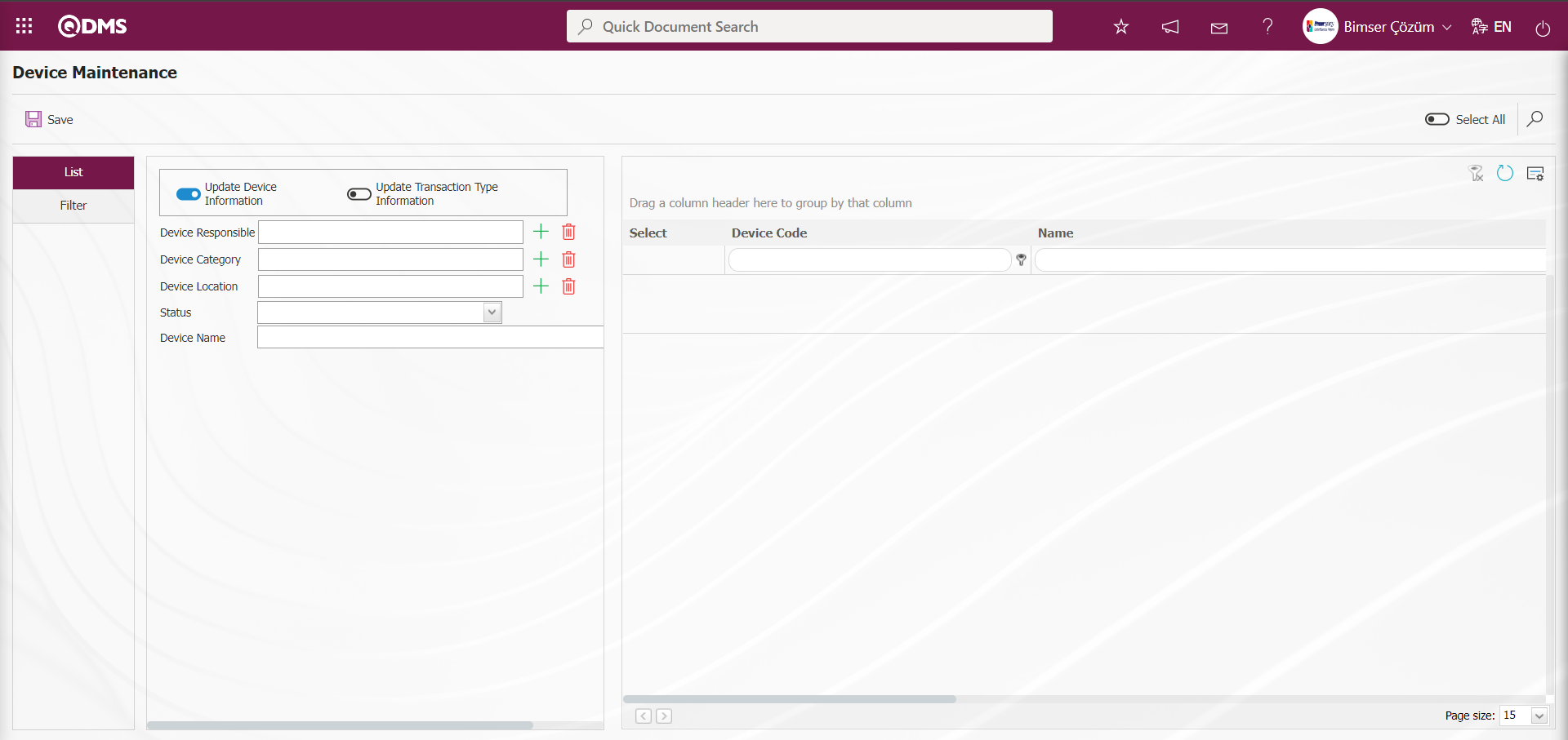
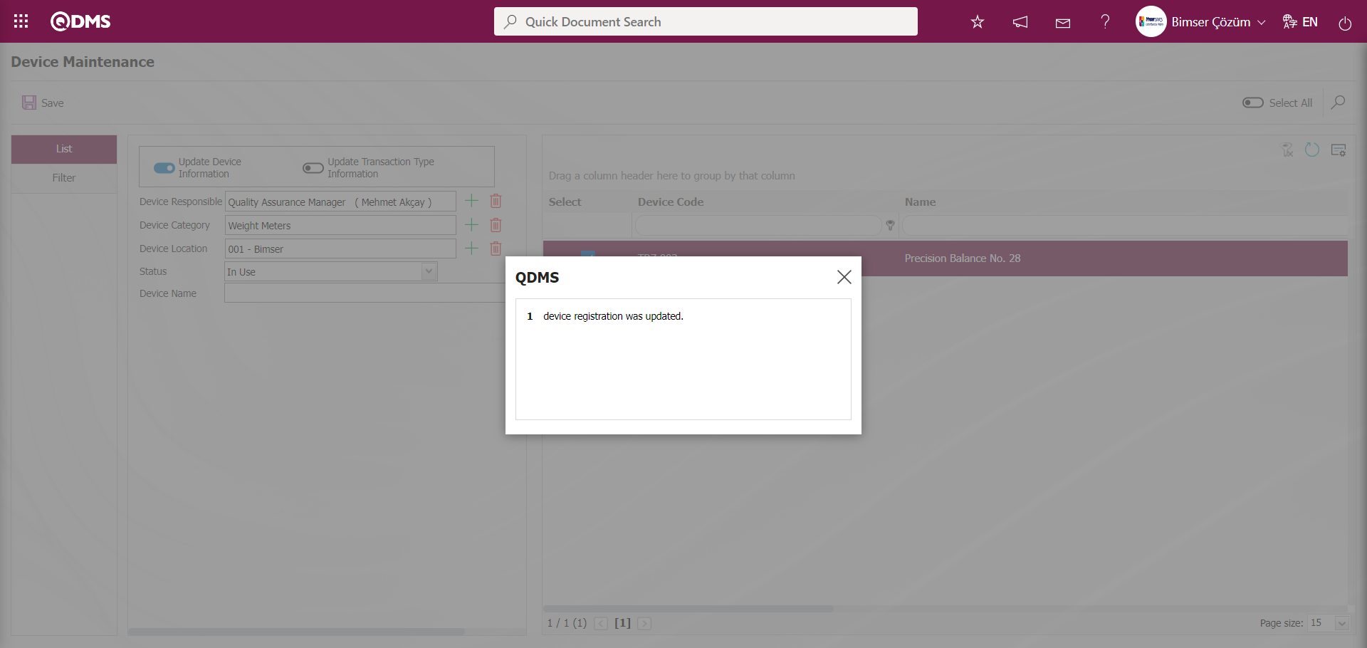
Device information update process is performed. After opening the device maintenance screen, the devices are listed by pressing the  (Search) button after the desired filtering on the filter screen. After selecting the devices to be modified (all listed devices can also be selected by checking the check box related to “Select All”). In updating device information, changes and updates can be made by selecting the device responsible, device category, device location, status and device name fields from the list defined in the system.
Related fields are defined on the screen that opens:
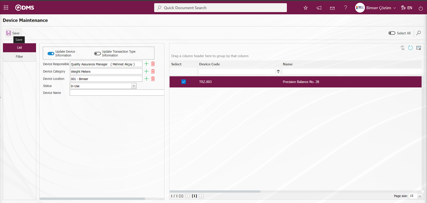
Device Responsible: This is the field where the responsible person of the device is selected from the list of positions defined in the system opened by clicking the  (Select) button in the list tab on the Device Maintenance screen.
Device Category: This is the field where the category of the device is selected from the list of categories defined in the system opened by clicking the (Select) button on the list tab on the Device Maintenance screen.
Device Location: It is the field where the location of the device is selected from the company profile list defined in the system opened by clicking the (Select) button on the list tab on the Device Maintenance screen.
Status: It is the field where the status of the device is selected from the status options such as scrap, in use in the status list opened by clicking the drop-down list on the list tab on the Device Maintenance screen.
Device Name: This is the field where the name of the device is written in the list tab on the Device Maintenance screen.
After the required fields are filled in, the device maintenance device information update registration process is performed by clicking the button in the upper left corner of the screen.
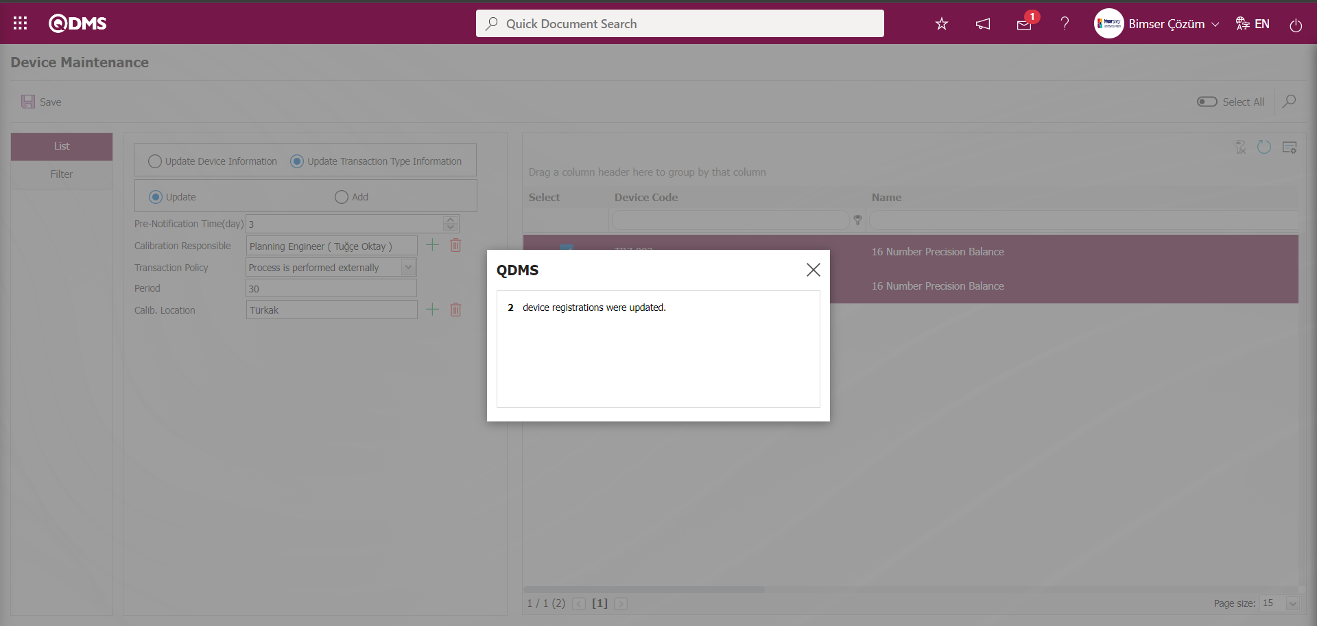
Update Transaction Type Information: Operation to update transaction type information is performed. Updates the existing transaction type. After the device maintenance screen is opened, after the desired filtering is made on the filter screen, the devices are listed by pressing the (Search) button. After selecting the devices to be modified (all listed devices can also be selected by checking the check box related to “Select All”). In updating the process type information, the period, calibration responsible and process policy fields can be selected from the list defined in the system and changes and updates can be made.
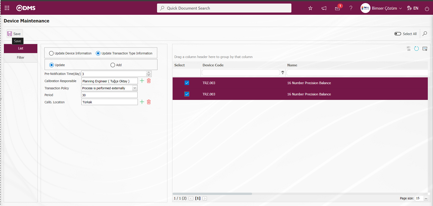
Related fields are defined on the screen that opens:
Pre-notification Period (day): This is the field where the pre-notification period of the device is selected in days in the list tab on the Device Maintenance screen.
Calibration Responsible:It is the field where the calibration responsible of the device in the list tab on the Device Maintenance screen is selected from the position list defined in the system opened by clicking the (Select) button.
Transaction Policy: It is the field where the transaction policy is selected from the list opened by clicking the drop-down list of the device in the list tab on the Device Maintenance screen. Process policy; “Process is performed internally”, “Process is performed externally”, “Process is performed internally and externally” and “Process cannot be tracked periodically” options can be selected.
Period: It is the field where the period information of the transaction type of the device is written in the list tab on the Device Maintenance screen.**
Calib. Location: It is a field displayed on the list tab on the Device Maintenance screen depending on the process policy options. When the “Process is performed internally” option is selected, a selection is made from the company profile list defined in the system by clicking the (Select) button. When the “Process is performed externally” option is selected, a selection is made from the list of processing locations defined in the system by clicking the (Select) button. When the “Process is performed internally and externally” option is selected, select from the company profile list defined in the system opened by clicking the (Select) button. When the “Process cannot be tracked periodically” option is selected, select from the company profile list defined in the system opened by clicking the (Select) button.
After the required fields are filled in, the device maintenance registration process is performed by clicking the button in the upper left corner of the screen.
Update Transaction Type Information/Add: It is used to add a new transaction type. Transaction Type, period, calibration Responsible, Transaction Policy, Latest Calib. Date and Date of next calibration fields can be added.
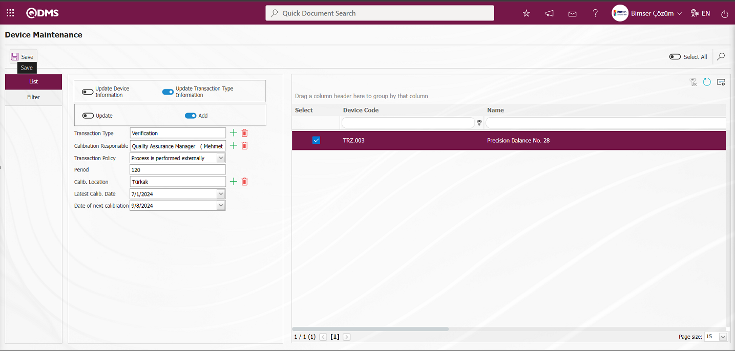
Related fields are defined on the screen that opens:
Transaction Type: It is the field where the transaction type of the device is selected from the list of transaction types defined in the system opened by clicking the (Select) button on the list tab on the Device Maintenance screen.
Calibration Responsible: This is the field where the operation responsible of the device in the list tab on the Device Maintenance screen is selected from the system-defined Position list opened by clicking the  (Select) button.
Transaction Policy: It is the field where the transaction policy is selected from the list opened by clicking the drop-down list of the device in the list tab on the Device Maintenance screen. Process policy; “Process is performed internally”, “Process is performed externally”, “Process is performed internally and externally” and “Process cannot be tracked periodically” options can be selected.
Period:It is the field where the period information of the transaction type of the device is written in the list tab on the Device Maintenance screen.
Calib. Location: It is a field displayed on the list tab on the Device Maintenance screen depending on the process policy options. When the “Process is performed internally” option is selected, a selection is made from the company profile list defined in the system by clicking the (Select) button. When the “Process is performed externally” option is selected, a selection is made from the list of processing locations defined in the system by clicking the (Select) button. When the “Process is performed internally and externally” option is selected, select from the company profile list defined in the system opened by clicking the (Select) button. When the “Process cannot be tracked periodically” option is selected, select from the company profile list defined in the system opened by clicking the (Select) button.
Latest Calib. Date: This is the field where the last date of the operation performed on the device in the list tab on the Device Maintenance screen is selected in the drop-down Calendar field.
Date of next calibration:In the list tab on the Device Maintenance screen, the Date of next calibration of the device is selected in the drop-down Calendar field.
After the required fields are filled in, the device maintenance registration process is performed by clicking the button in the upper left corner.
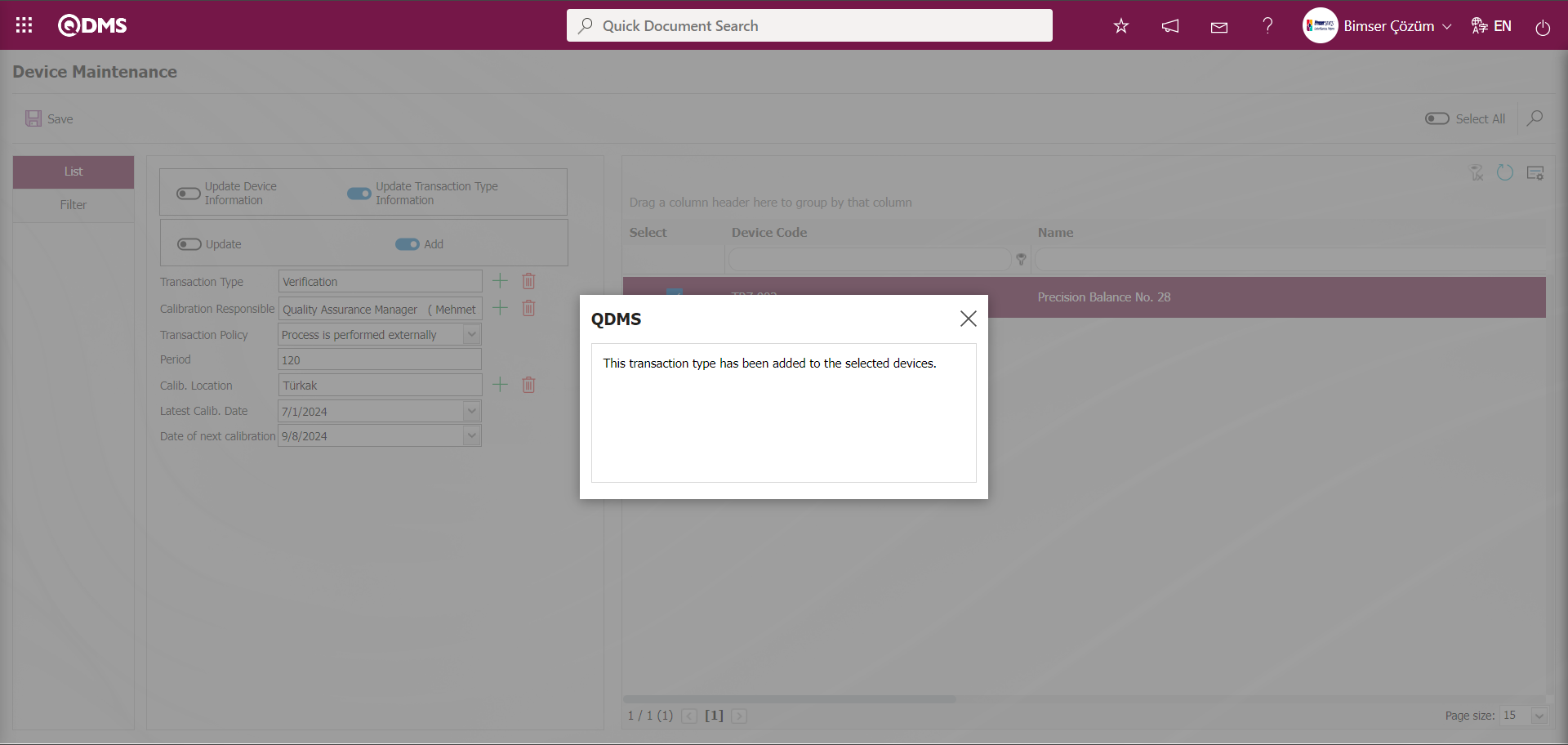
“This transaction type has been added to the selected devices.” message is given by the system, indicating that the transaction type has been added for the selected device on the device maintenance screen.
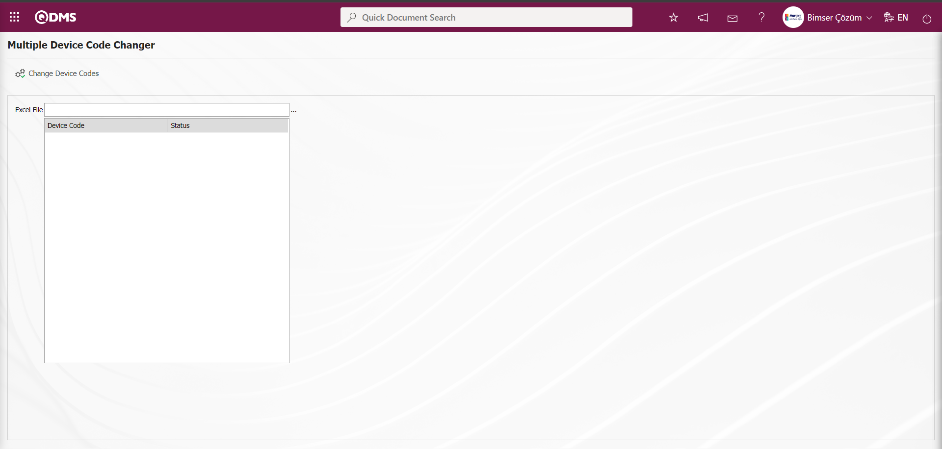
6.1.8. Multiple Device Code Replacement
Menu Name: System Infrastructure Definitions/ Device Management System/ Multiple Device Code Replacement
This is the menu where the process of changing device codes in multiple ways is realized. Users do not perform any operation in this menu and the process of changing device codes in multiple ways is done by Bimser Support System through the server.
6.1.9. Device Management Parameters
Menu Name: System Infrastructure Definitions/ Device Management System/ Device Management Parameters
It is the menu where the system settings of the Device Management Module are made according to the user's requests and needs and the parameters are determined accordingly.

With the help of the buttons on the screen;
 : Changes and edits are made on the parameter selected in the list.
 : Records are filtered and searched.
: The search criteria on the menu screens are used to clear the data remaining in the filter fields in the grid where the search operation is performed.
: The menu screen is restored to its default settings.
: User-based designing of the menu screen is done with the show-hide feature of the fields corresponding to the columns on the menu screens, that is, the hiding feature.
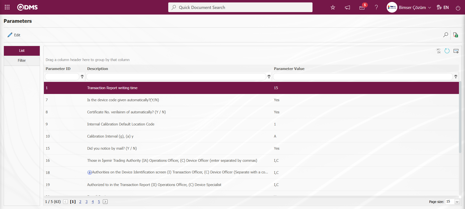
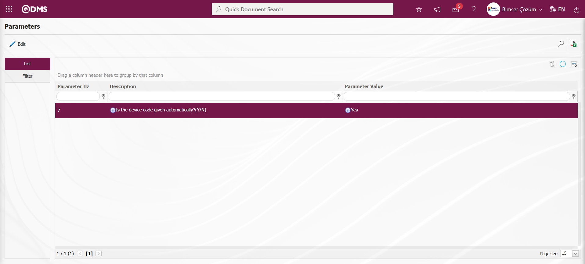
On the Parameters screen, click the  button while parameter 7 is selected in the list tab.
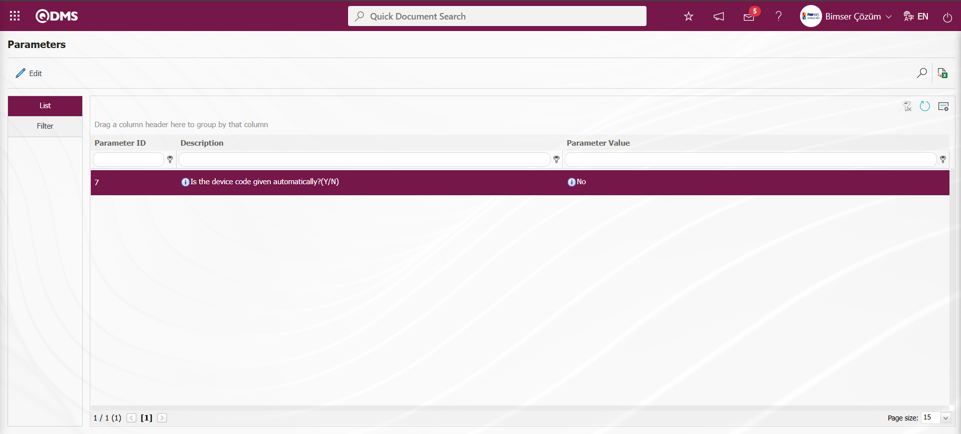
In the parameters screen, the parameter value information of the parameter “Is the device code given automatically?(Y/N)” is changed. If desired, the default value information about the parameter value of the parameter is provided by clicking the  button on the parameters screen.
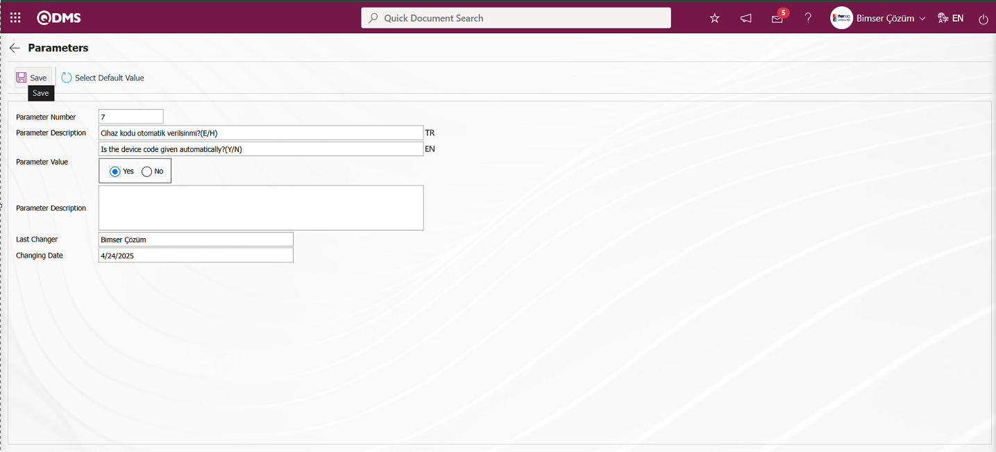
In the Parameters screen that opens, the parameter value of the parameter is selected as “Yes” and after entering the relevant information in the required fields, the parameter record update process is performed by clicking the button in the upper left corner of the screen.
By clicking the  button on the Parameters screen, operations such as activating the parameter by selecting the parameter value of the selected passive parameter “Yes”, deactivating the parameter by selecting the parameter value of the selected activated parameter “No”, changing the parameter value of the selected parameter, if any, and selecting the default value of the selected parameter are performed.
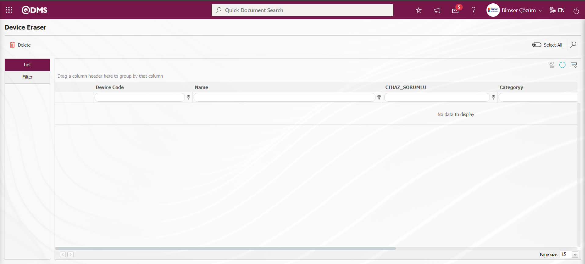
6.1.10. Device Eraser
Menu Name: System Infrastructure Definitions/ Device Management System/ Device Eraser
This is the menu where device deletion from the system is performed. It allows the devices to be deleted from the system so that they are not used.
With the help of the buttons on the screen;
 : Delete the selected device in the list.
 : Records are filtered and searched.
: The search criteria on the menu screens are used to clean the data remaining in the filter fields in the grid where the search operation is performed.
: The menu screen is restored to its default settings.
: User-based designing is done on the menu screen with the show-hide feature, that is, the hiding feature of the fields corresponding to the columns on the menu screens.
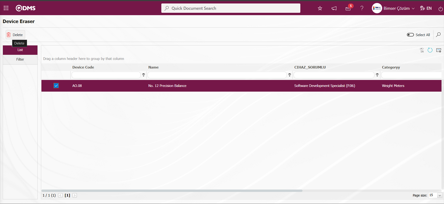
On the Device Deleter screen, select the device you want to delete from the device list in the list tab, then click the button to delete the device.
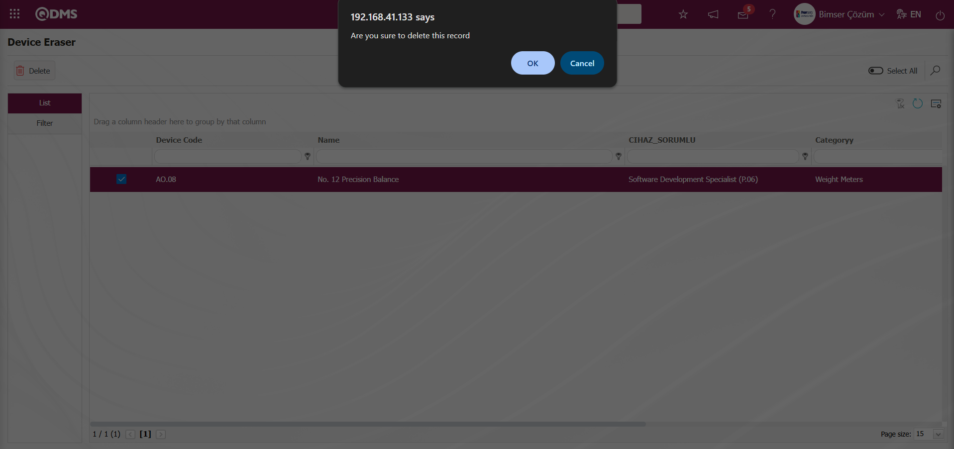
In the message “Are you sure to delete this record” given by the system, the “OK” button is clicked and the device is deleted.
6.1.11. Batch Transfer of Devices
Menu Name: System Infrastructure Definitions/ BSID/ Configuration Settings/ Transfers/Device Transfer
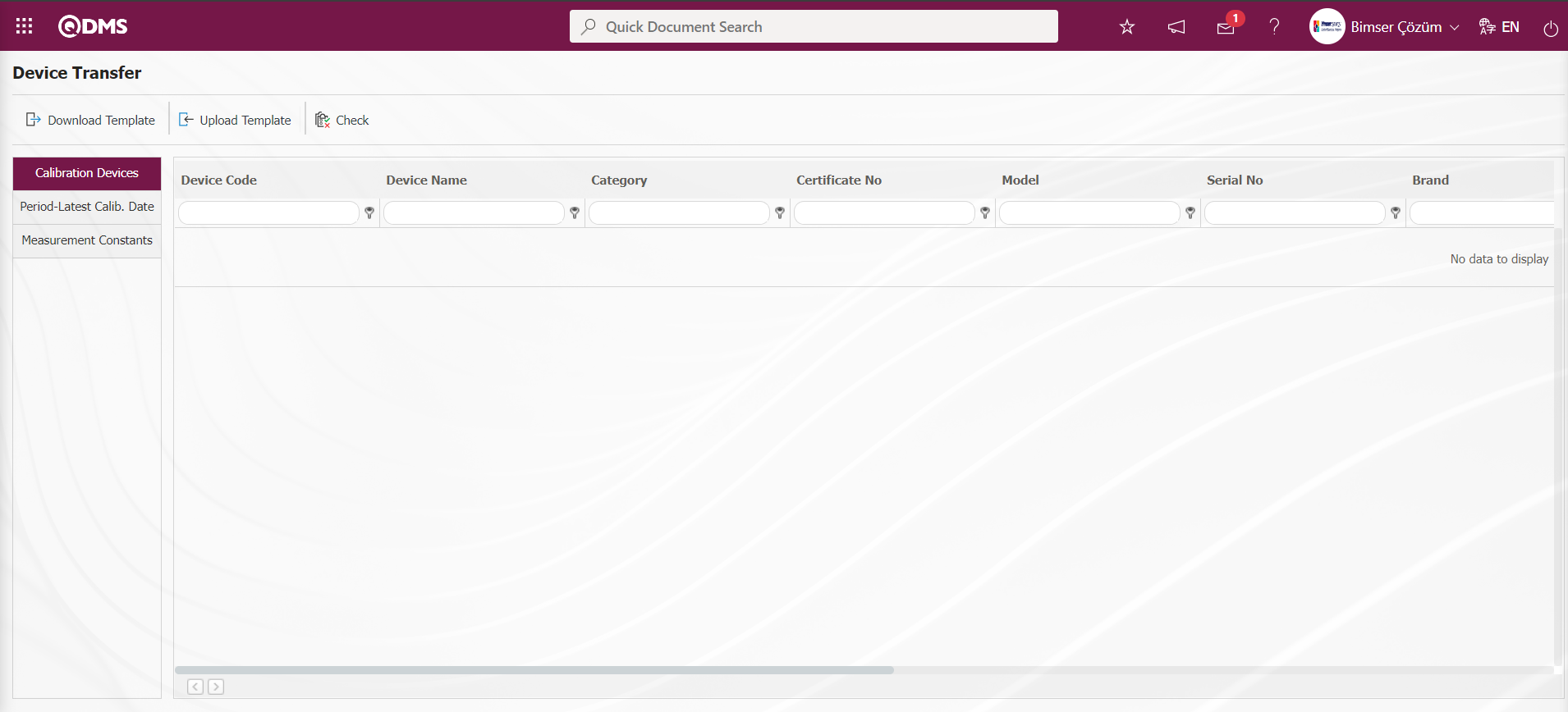
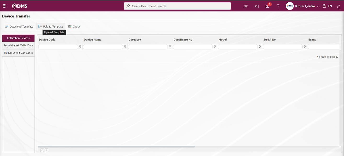
It is the menu where the devices processed in the Device Management module are transferred to the system in bulk.
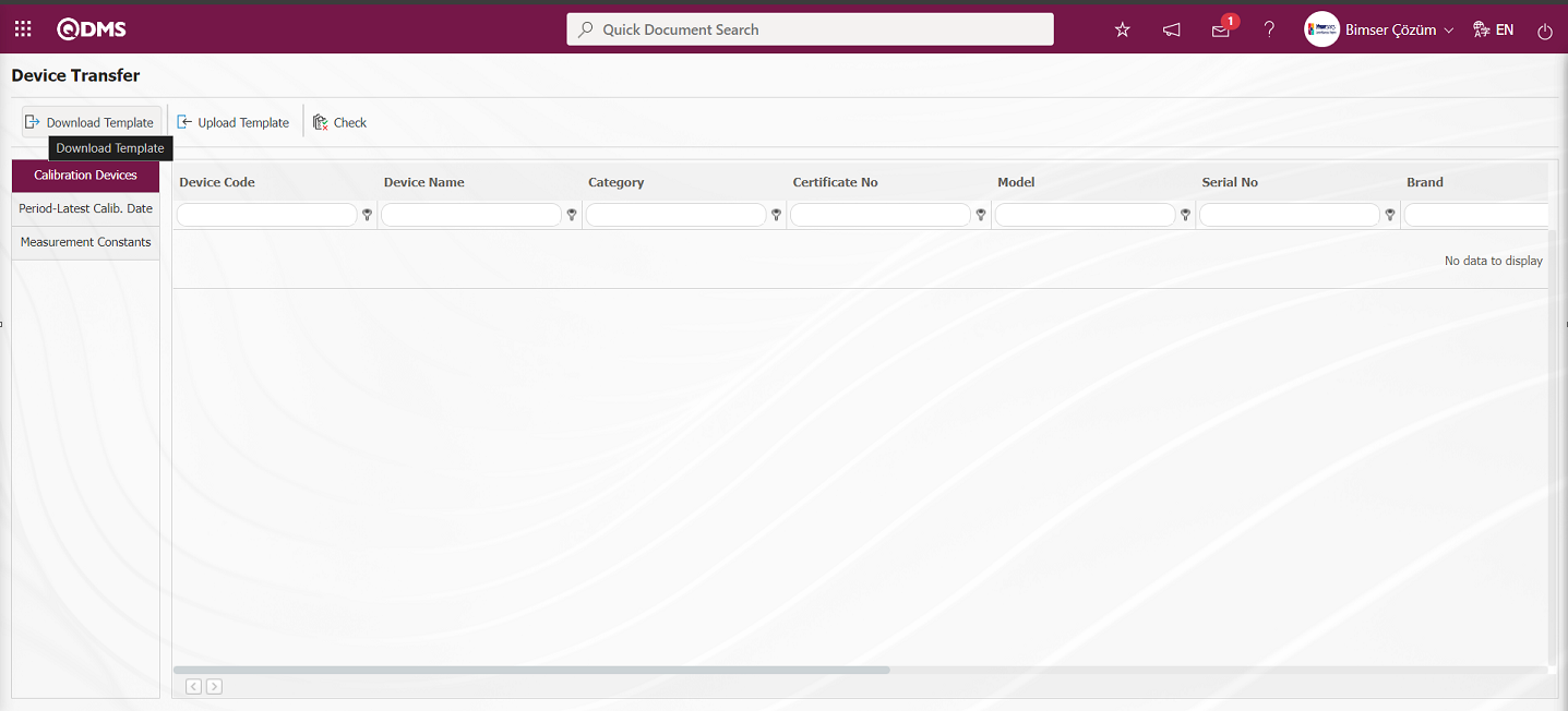
With the help of the buttons on the screen;
 Device Transfer template is downloaded to the computer.
 : The filled Device Transfer template is uploaded to the system.
 : Check whether the Device Transfer template filled and uploaded to the system gives an error or not.
 : The transfer process is performed.
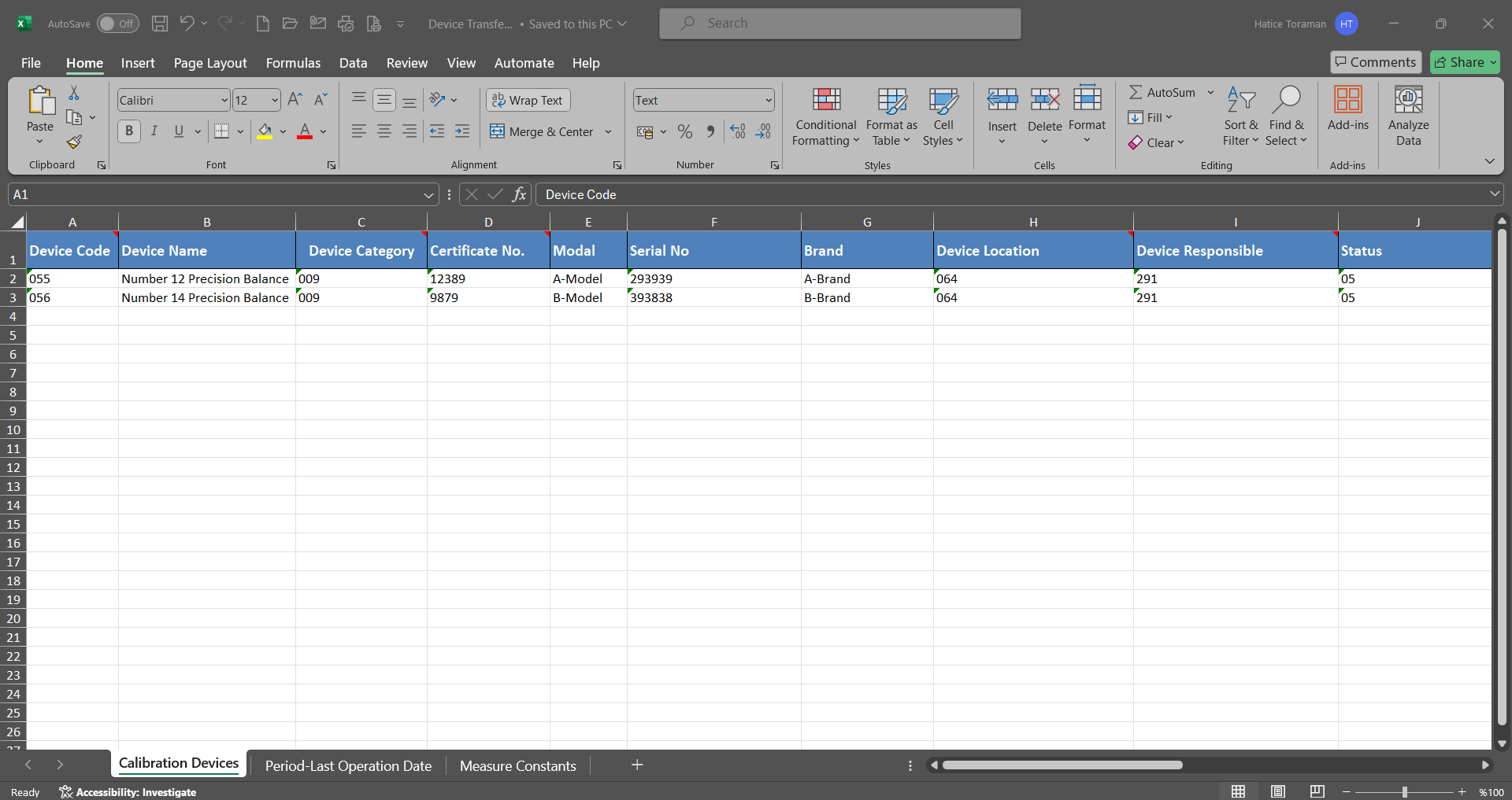
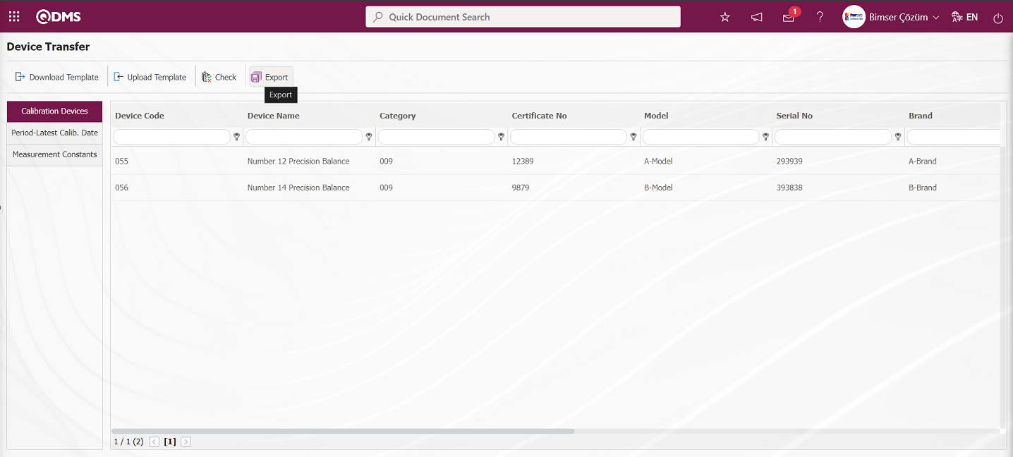
The Device Transfer template is downloaded with the button on the screen, after filling in the necessary information, the Device Transfer template is uploaded to the system with the button. In order to check the entered information, the button is used. If the transferred data is suitable for transfer, the device transfer process is realized via the button.
Device Transfer template is downloaded to the computer with the button on the Device Transfer screen. The relevant fields in the Device Transfer template are saved to the computer by typing the relevant information.
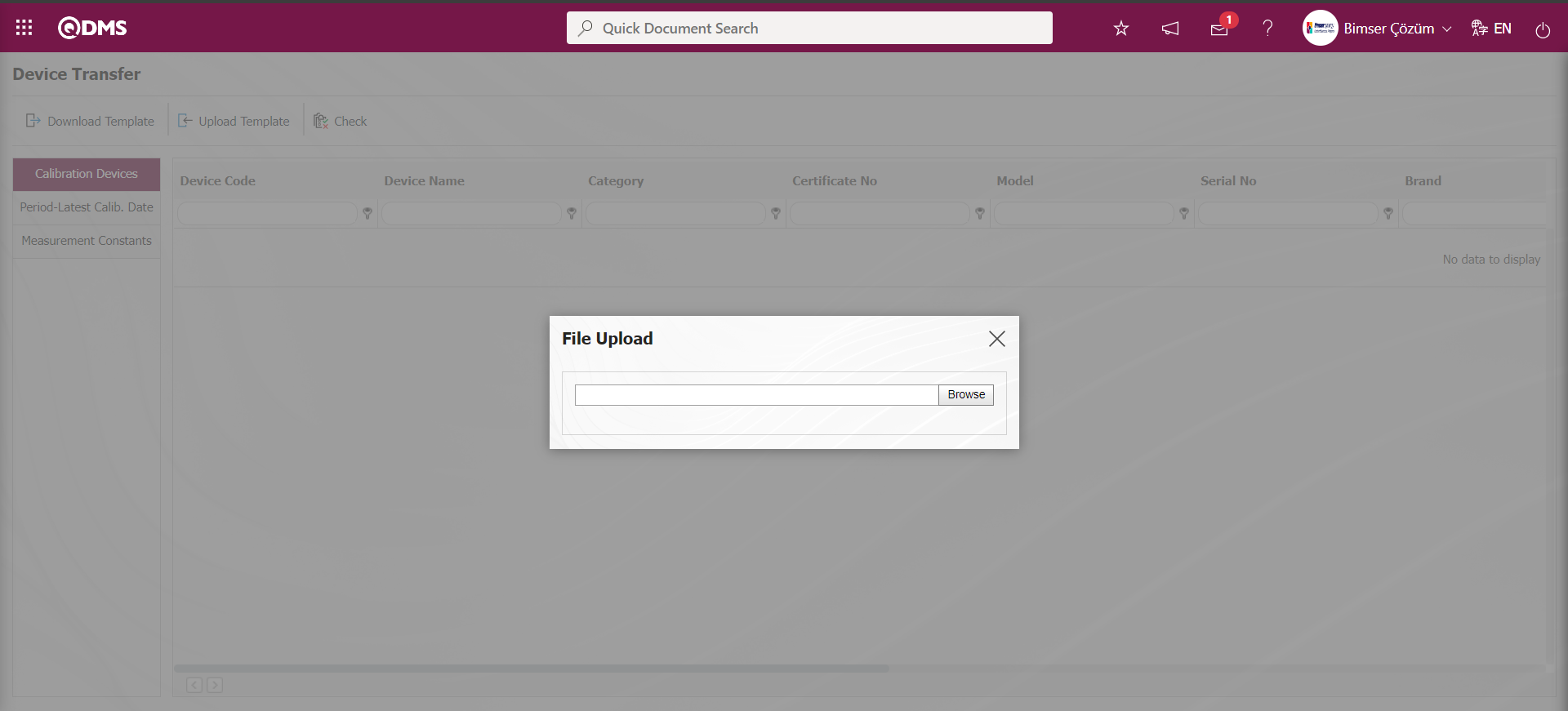
Click the  button on the Device Transfer screen.
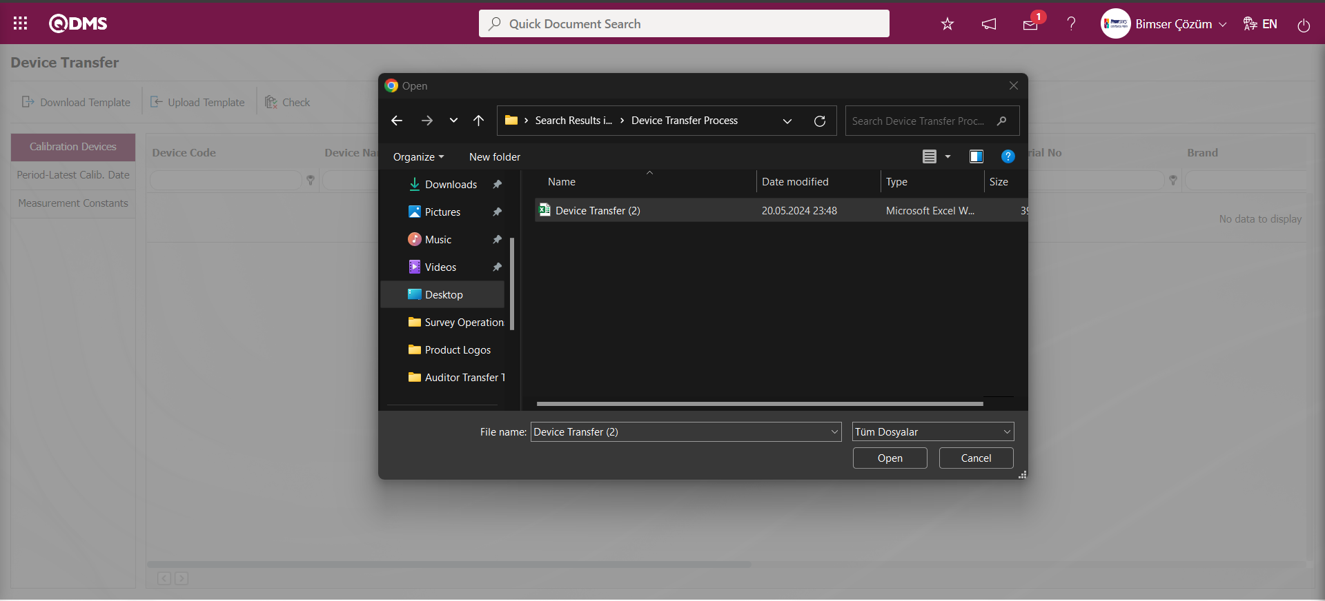
Click the  button on the Upload File screen
 Select the filled Device Transfer template on the screen that opens.
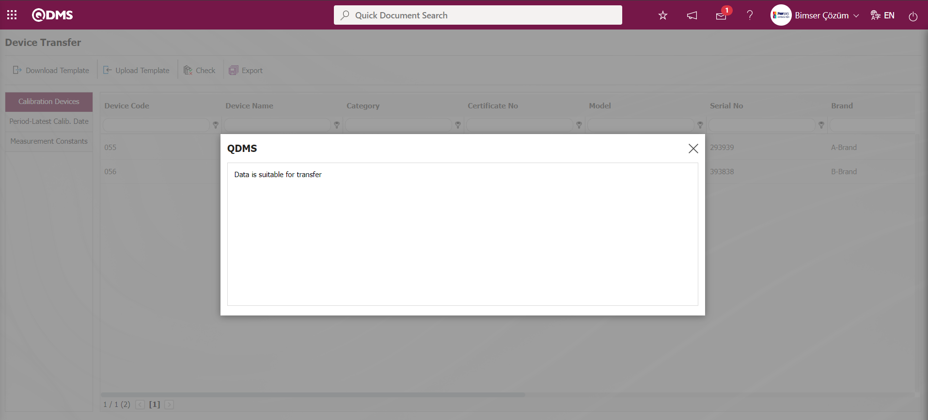
On the Device Transfer screen, the button is clicked to check whether the template created and uploaded to the system gives an error or not.
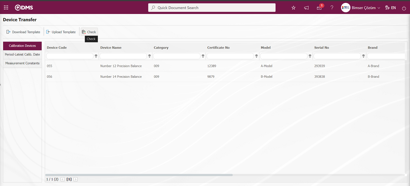
The system displays the message “Data is suitable for transfer”.
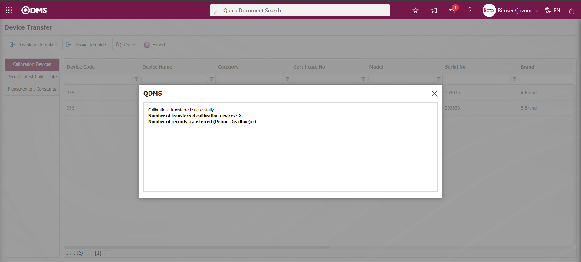
On the Device Transfer screen, the Device Transfer operation is performed by clicking the button.
“Calibrations successfully transferred” message is given by the system and the number of devices transferred is included in the message.
6.1.12. Device Management System Module Field Identification Process for Common Use
Menu Name:System Infrastructure Definitions/BSID/Configuration Settings/Language Settings
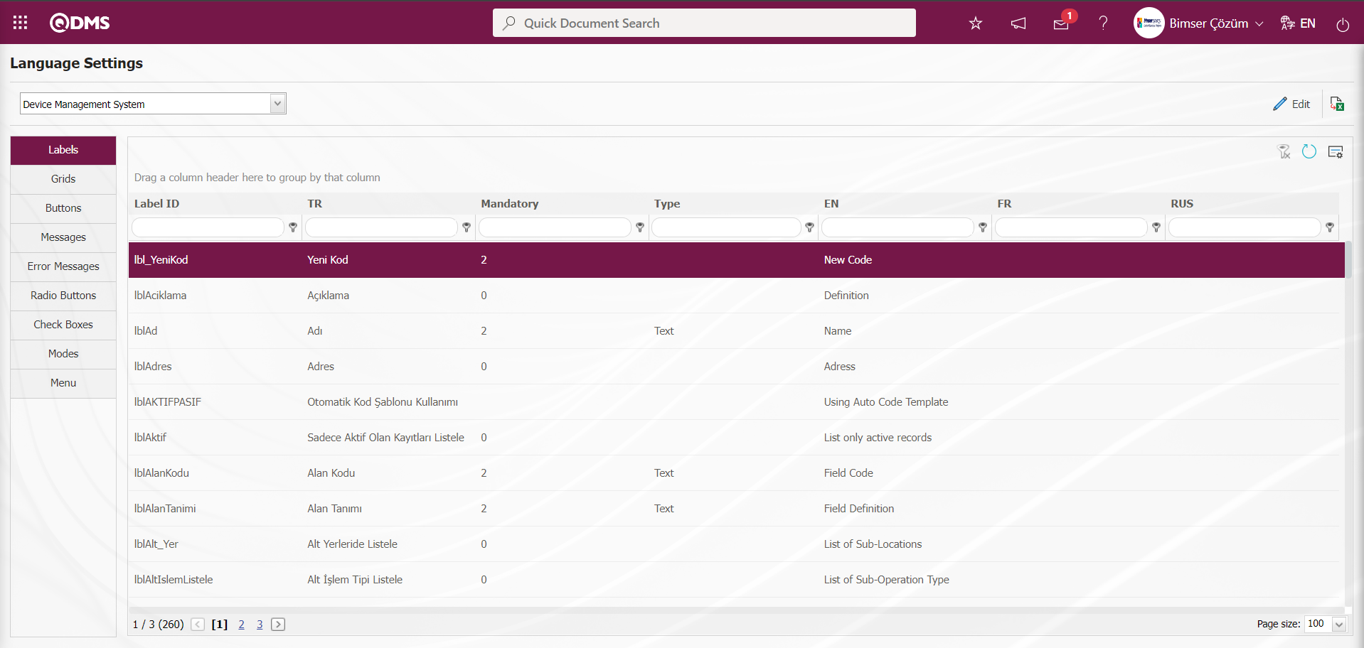
In the Device Management System Module, extra fields that are not in the system requested by the company can be defined in the Device Categories / Measurement Constants and Calibration Report / Measurement Values tab in the Other Information tab for the Device Definition menu. These defined fields are valid for all Device Management System Module resources. Click on System Infrastructure Definitions/BSID/ Configuration Settings/Language Settings menu. On the Language Settings page, select “Device Management System” in the Module field and the language definitions related to the Device Management System Module are displayed on the screen.
In the Device Management System Module, parametric fields are defined from the Language settings in the Other Information tab based on the Integrated Management System / Device Management System / Device Definition menu. The fields defined in the Device Management System System Infrastructure Definitions / BSID / Configuration Settings / Language Settings are located in the Other Information tab on the Device Definition page opened by clicking the  button on the Device list screen opened in the Device Definition menu, as well as the definitions of some parametric fields are displayed on the Device Categories and Calibration Report Definition screens. In the Device Categories menu, the parametric fields in the language settings defined on the Measurement Constants page, which is opened by clicking the
  button on the measurement constants screen opened by clicking the Measurement Constants button. In the Calibration Report menu, the parametric fields defined in the Language settings are displayed on the Measurement Values Definition page opened by clicking the button on the Measurement Values tab on the Process Report screen
Parametric Type Fields and Definitions Defined in Device Management System Module
1-Date type: Calendar field is the added parametric field. Example Short Code: lblDPARAM1 (displayed in Device Definition/Other Information tab)
2-List type: It is a parametric field that allows a single selection from multiple list elements. List elements are defined and selected from the defined list elements. Example Short Code: lblLPARAM1 (displayed in Device Definition/Other Information tab), Example Short Code: lblOS_LParam1 (displayed in Device Category/Measurement Constants Definition and Calibration Report/Measurement Values Definition screens).
3-Staff Type: Allows to select a person from QDMS Staff database. A selection is made in the list of Personnel defined in the System Infrastructure Definitions/BSID/ Identification/Personnel Identification menu. Example Short Code: lblPPPARAM1 (displayed in Device Definition/Other Information tab)
4-Text Type: It is a parametric field that adds a text box that allows manual typing. Example Short Code: lblPARAM1 (displayed in Device Definition/Other Information tab)
5- Unit of MeasureTyped: It is the parametric field that allows data entry as measurement. Next to the defined parametric field, the Units of Measure selection field appears. Units of measure in the Units of measure selection field are the units of measure defined in the System Infrastructure Definitions/BSID/Definitions/Define Units of Measure menu. Example Short Code: lblNPARAM1 (displayed in Device Definition/Other Information tab)
6-Document (Multi Select) Type: It is a parametric field that allows multiple-single selection of document information from QDMS document database. Example Short Code: lblDOCPARAM1 (displayed in Device Definition/Other Information tab)
7- Text (Multiple Line) Type: It is a parametric field that allows manual typing and adds a multi-line text box with no character limit. Example Short Code: lblMPARAM1 (displayed in Device Definition/Other Information tab)
8-Numeric Type: It is a parametric field that allows numeric data entry. Example Short Code: lblOS_NParam1 (Displayed on Device Category / Measurement Constants Definition and Calibration Report / Measurement Values Definition screens).
Defining a Date-type Parametric Field in the Device Definition/Other Information Tab in the Device Management System Module
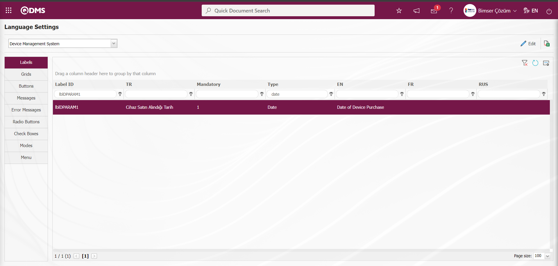
List of Date Type Parametric Fields
In order to define a parametric field with date type in the Other Information tab in the Integrated Management System / Device Management System / Device Definition menu in the Device Management System Module, first of all, by coming to the System Infrastructure Definitions / BSID / Configuration Settings / Language Settings menu and typing Date in the type field, date-type parametric fields are searched and the list of date-type parametric fields is listed in the Language Settings menu. Field definition of the listed date type parametric fields is made.
Date Type Parametric Field Definition
lblDPARAM1 Date type parametric field is selected and  button is clicked for data entry of the field.

On the screen that opens, type the field name we want to see in the value field.
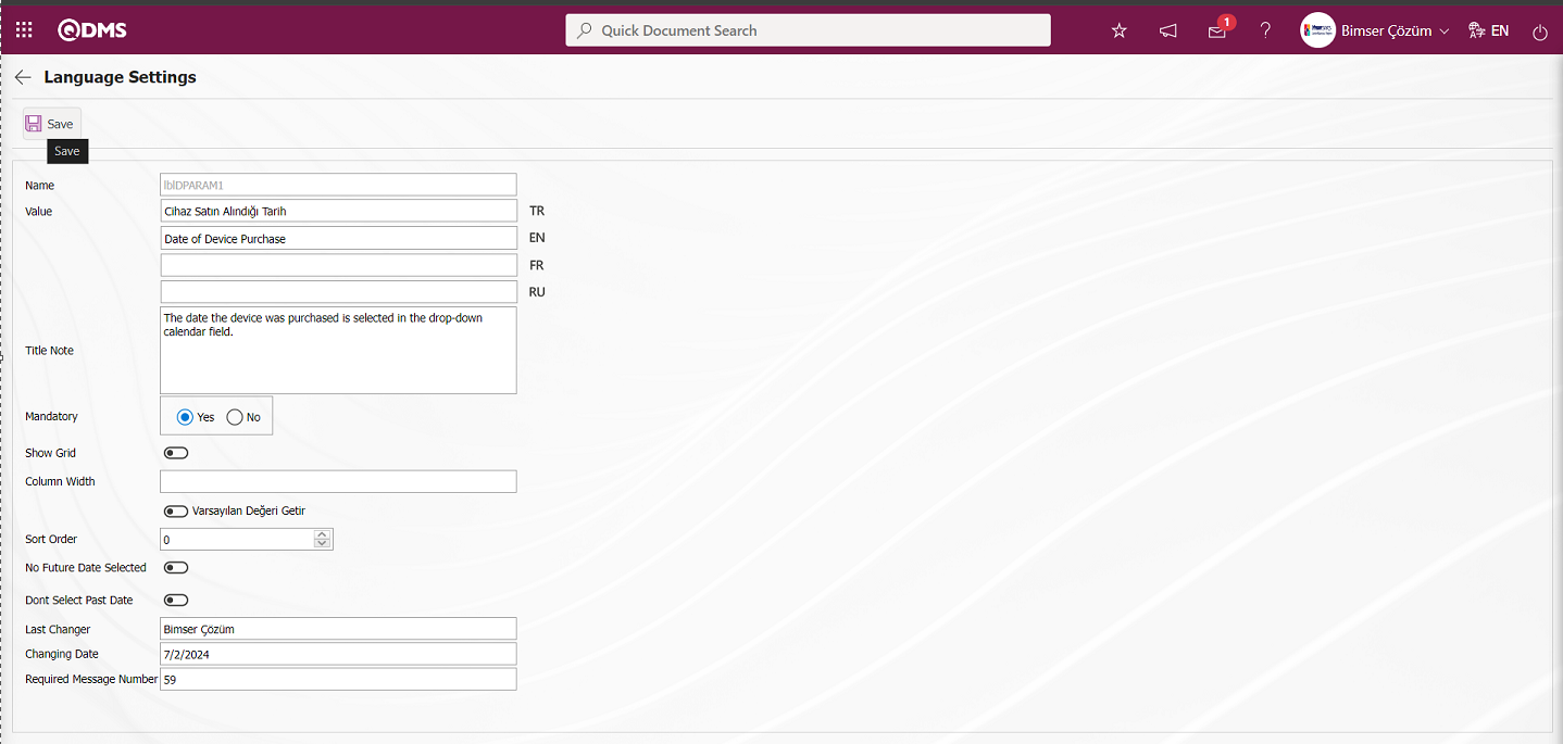
Date type parametric field definition registration process is performed by filling in the required fields such as whether the field will be mandatory or not and clicking the  button. In the same way, the definition process of other parametric field types is defined by performing the same process steps.
The defined “Date of Device Purchase” date-type parametric field is displayed in the Other Information Tab of the Integrated Management System/Device Management System/Device Definition menu.
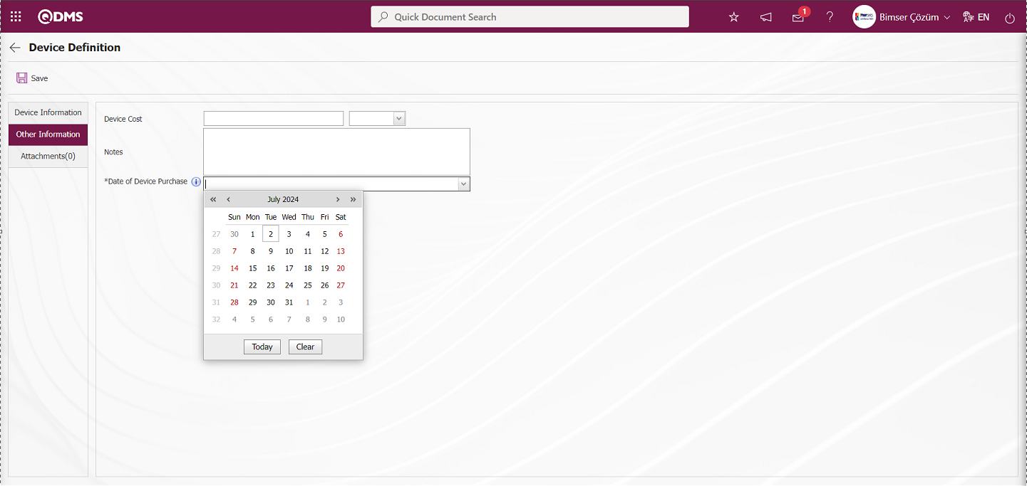
It is seen that the date-type parametric field defined in the Other Information tab on the Device Definition screen is a mandatory field with an asterisk and when the mouse hovers over it, the title note information is displayed.
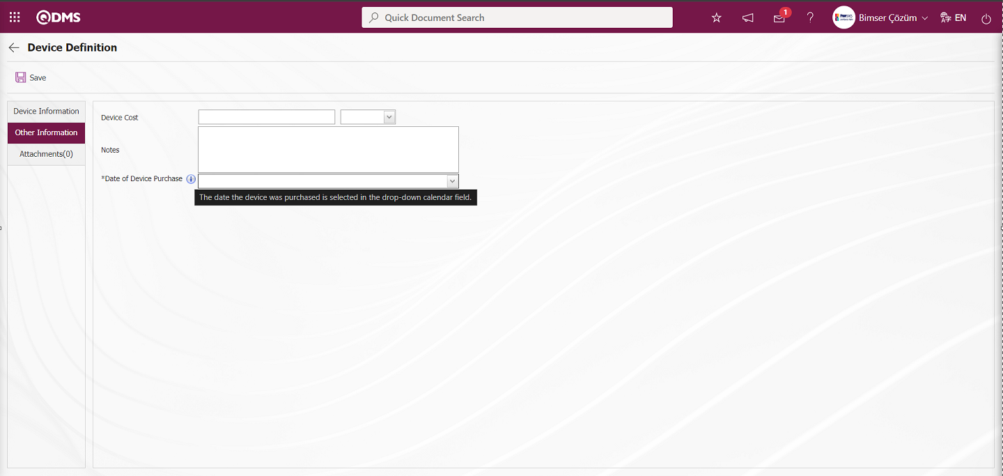
6.2. Integrated Management System/ Device Management System
Device System Management Module's Define Device, Fulfill operation, Operation History menus are the part where realization and reports are displayed.
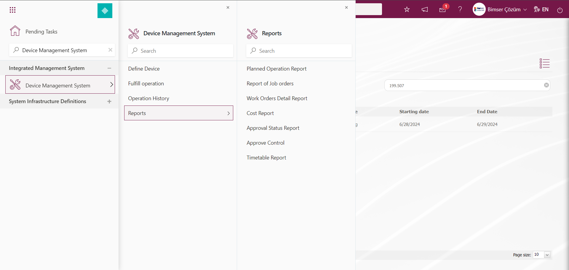
6.2.1. Define Device
Menu Name: Integrated Management System/ Device Management System/ Device Definition
This is the menu where Device Definition process is done. Two tabs, Filter and List, appear on the Device List screen. In the Filter tab, filtering is done according to the search criteria. List tab displays the list of defined devices. Operations such as updating, copying, deleting operations, defining measurement constants, adding operation types and displaying the operation history if an operation has been performed on the device are performed with the help of the buttons.The list of defined devices is listed according to the states defined in the status definition menu such as in use, out of use, pending, scrap and defective. This coloring process is done in the System Infrastructure Definitions/Device Management System/Status Definition menu on the screen where the process of defining the states is done. The colors of the devices are determined in this menu in cases such as in use and scrap in the color field. Since the color of the device in the “in use” status in the system is defined as green in the Status definition menu, the devices in this status are displayed in green in the Device list. In the list tab on the device list screen, devices in other states are displayed in different colors.
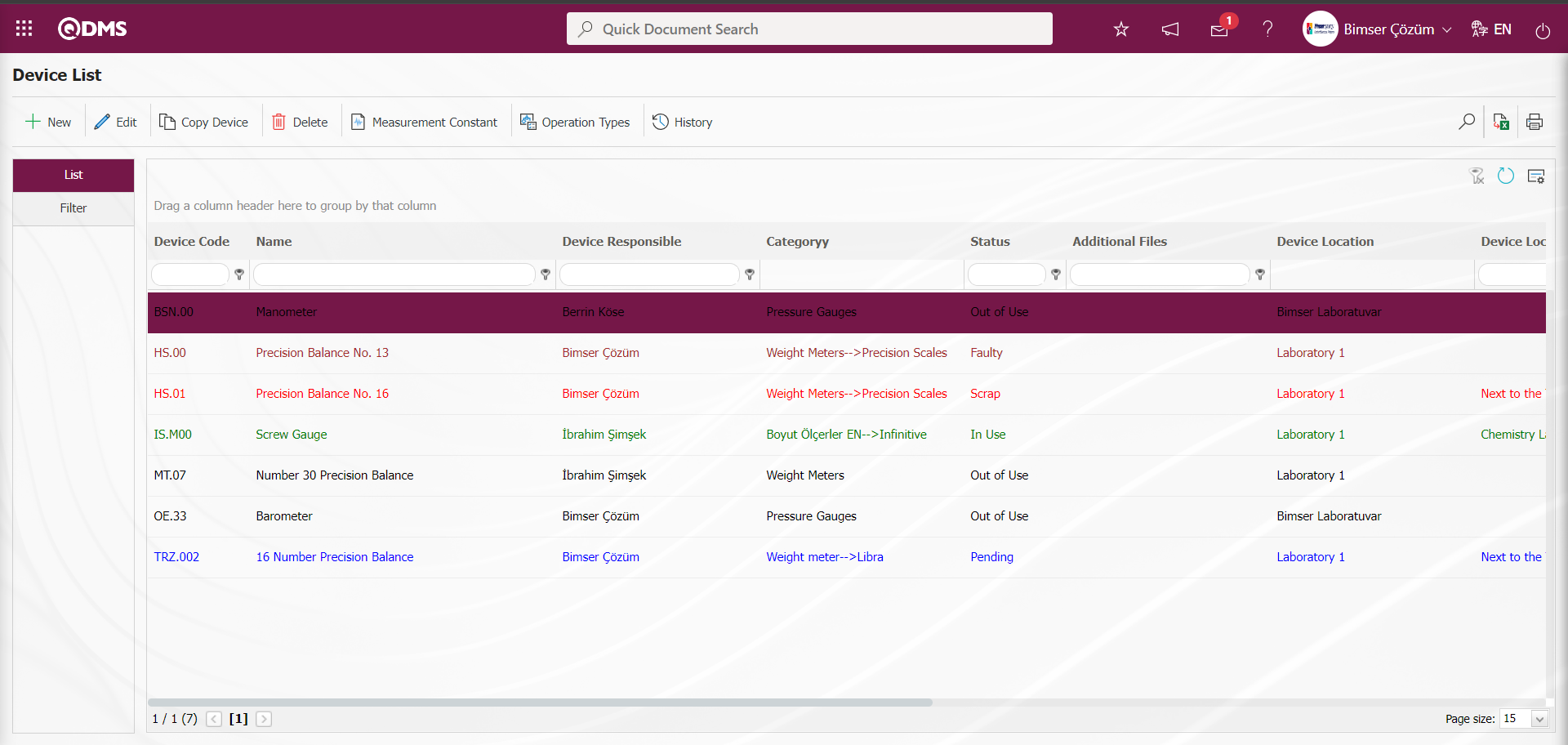
In the Filter tab, the status field is filtered according to the scrap search criteria and the  (Search) button is clicked.
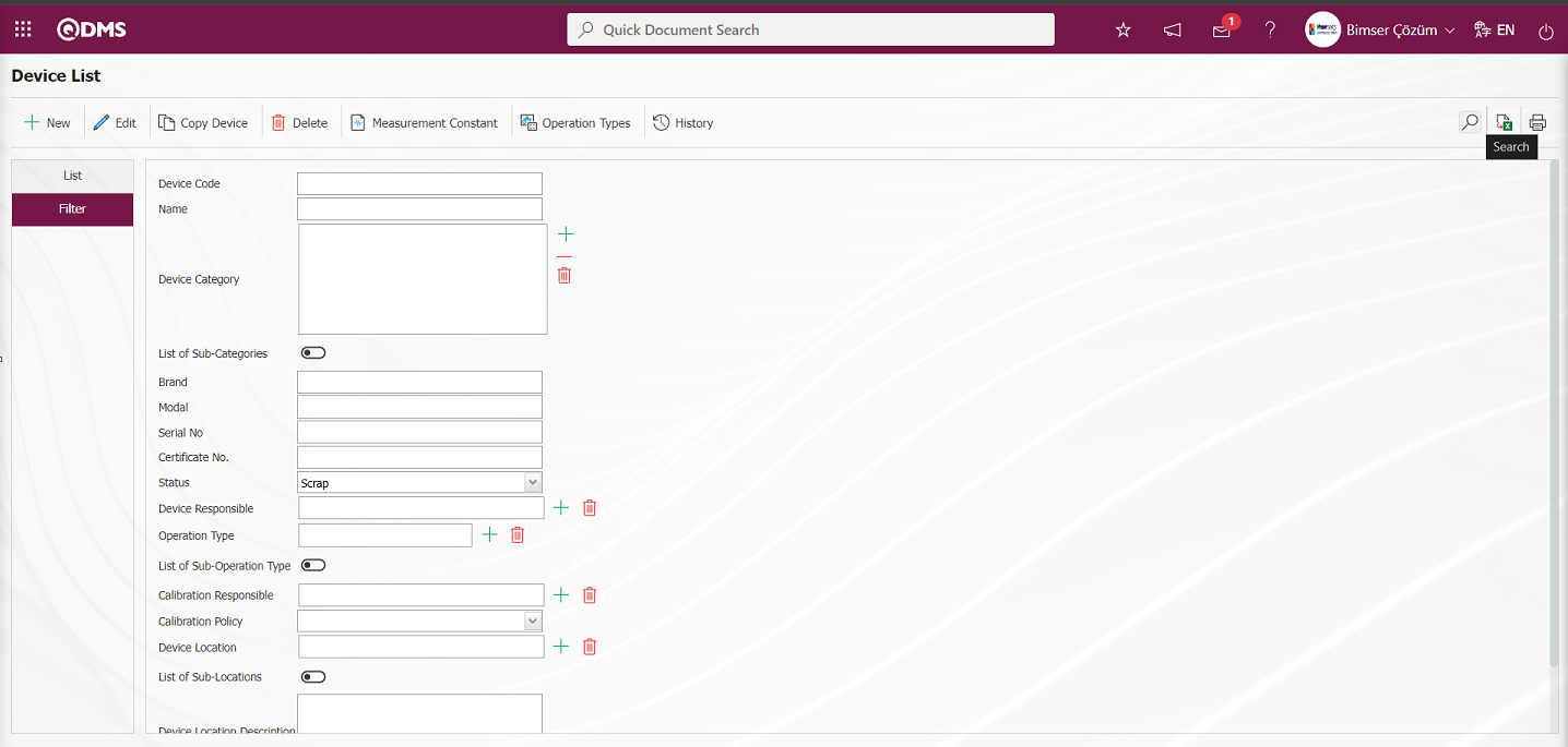
After the filtering process in the list in the device list tab, the devices whose status is Scrap are displayed in the list in red color. In the system, the color of the device in the “Scrap” status is defined as Red in the Status Definition menu and it is displayed in Red color in the Device list.
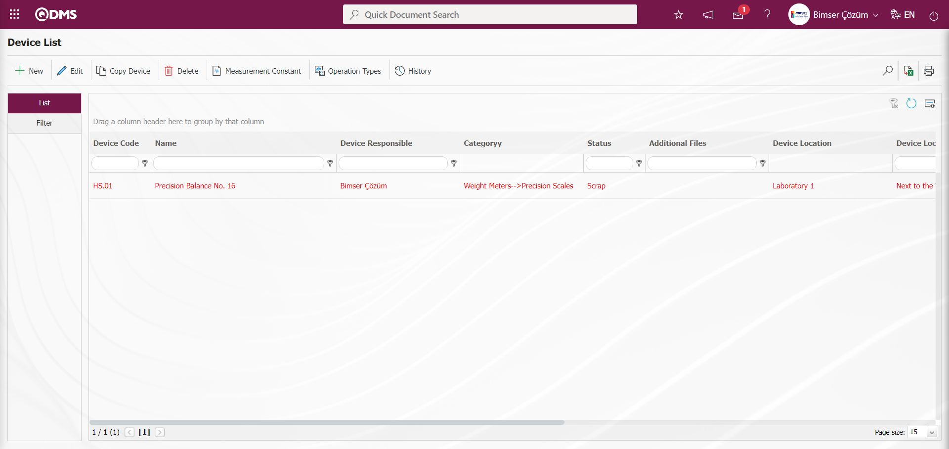
With the help of the buttons on the screen;
 : Defining a new device is done.
 : Changes and updates are made on the device information selected in the list.
 : Deletes the device information selected in the list.
 : Copy the selected device information in the list. It is used to create a new device by copying the selected device.
 : Defining the measurement constants of the device selected in the list is done. If there are defined measurement constants, they are displayed.
 : Define the operation types of the selected device in the list. If there are defined operation types, they are displayed.
 : It is done to display the history of the operations performed on the device selected in the list.
 : Searches the device list according to the specified filtering criteria.
 : Transfers the device list to Excel.
 : Label printing of the device selected in the list is done.
 : Cleans the data remaining in the filter fields in the grid where the search criteria on the menu screens are searched.
 : The menu screen is restored to its default settings.
 : User-based designing of the menu screen is done with the show-hide feature, that is, the hiding feature of the fields corresponding to the columns on the menu screens.
To add a new device to the list, click the button at the top left corner of the screen to display the Device Definition screen.

There are 3 tabs on the Device Definition screen: Device Information, Other Information and Attachments
Device Information Tab: This is the tab where general information about the device such as category, code, name, brand of the device is written.
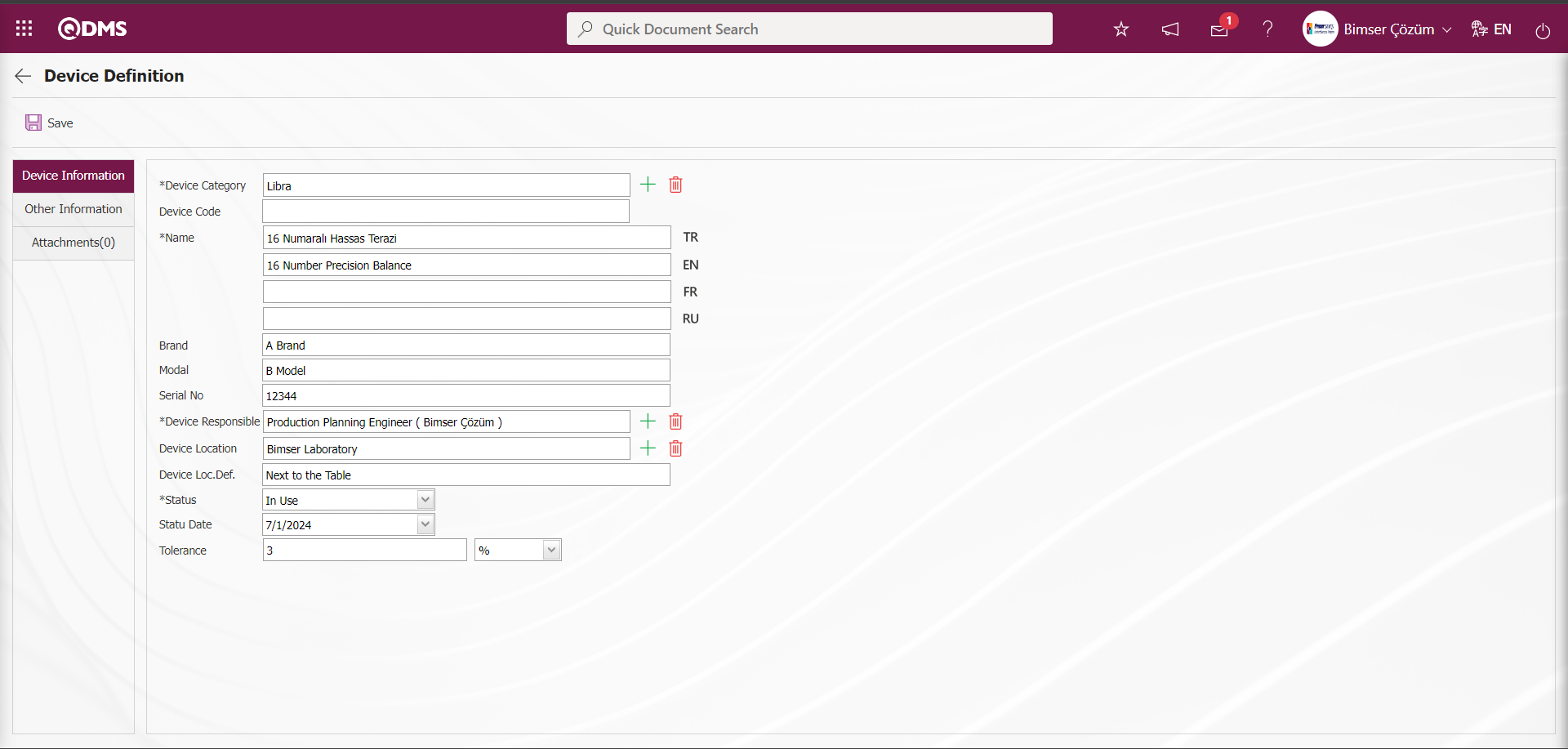
Related fields are defined on the screen that opens:
Device Category: This is the field where the category of the device defined in the Device Category list defined in the system, which is opened by clicking the (Select) button in the Device Information tab on the Device Definition screen. The category list of the device comes defined in the System Infrastructure Definitions / Device Management / Device Categories menu. It is selected from the category list.
Device Code: It is the field where the code of the device defined in the Device Information tab on the Device Definition screen is automatically given by the system according to the code template and counter value defined in the selected device category.
Name: This is the field where the name of the device defined in the Device Information tab on the Device Definition screen is written. In the field with the English language equivalent icon, the English language equivalent of the definition part of the device is written.
Brand: This is the field where the brand information of the device defined in the Device Information tab on the Device Definition screen is written.
Model: This is the field where the model information of the device defined in the Device Information tab on the Device Definition screen is written.
Serial No: This is the field where the serial number information of the device defined in the Device Information tab on the Device Definition screen is written.
Device Responsible: This is the field where the responsible person of the device defined in the Device Information tab on the Device Definition screen is selected from the list of positions defined in the system opened by clicking the  (Select) button. In this field, we determine the person who will make changes on the device by selecting the responsible person of the device from the list of positions defined in the system.
Device Location: It is the field where the device defined in the Device Information tab on the Device Definition screen is selected from the company profile defined in the system opened by clicking the (Select) button.
Device Location Description: This is the field where the location description information of the device defined in the Device Information tab on the Device Definition screen is written.
Status: It is the field where the status information of the device defined in the Device Information tab on the Device Definition screen is selected from the drop-down status list. The status list comes as defined from the System Infrastructure Definitions / Device Management / Status Definition menu. The status of the device such as scrap or in use can be selected.
Status Date: This is the field where the date on which the status of the device defined in the Device Information tab on the Device Definition screen is selected from the Calendar field.
Tolerance : The tolerance value of the device defined in the Device Information tab on the Device Definition screen is entered.
In the Device Information tab, there are fields such as device category, name, brand, model, device responsible. Device Code field is left blank, the system generates the code automatically. Select one of the predefined categories from the Device Category drop-down menu. According to the Tolerance percentage determined here, acceptance lower and acceptance upper ranges are automatically assigned in the measurement constants. Assuming that the Standard Value is 100 and the Tolerance value is 3%, the Acceptance Upper Range is assigned as 103 and the Acceptance Lower Range is assigned as 97.
Other Information tab: If there are parametric fields defined for the device, this tab contains them. In addition, information such as the cost information of the device and notes to be added about the device can be entered. Parametric fields can be created from the System Infrastructure Definitions/BSID/ Configuration Settings/ Language Settings menu. In the Language Settings menu, select the Device Management System module as the module. After selecting the Module Device Management System, the passive parametric field types to be defined in the Device Management System are displayed. From these passive parametric fields, parametric type fields such as text, date, list, etc. are defined and displayed in the Other Information tab.
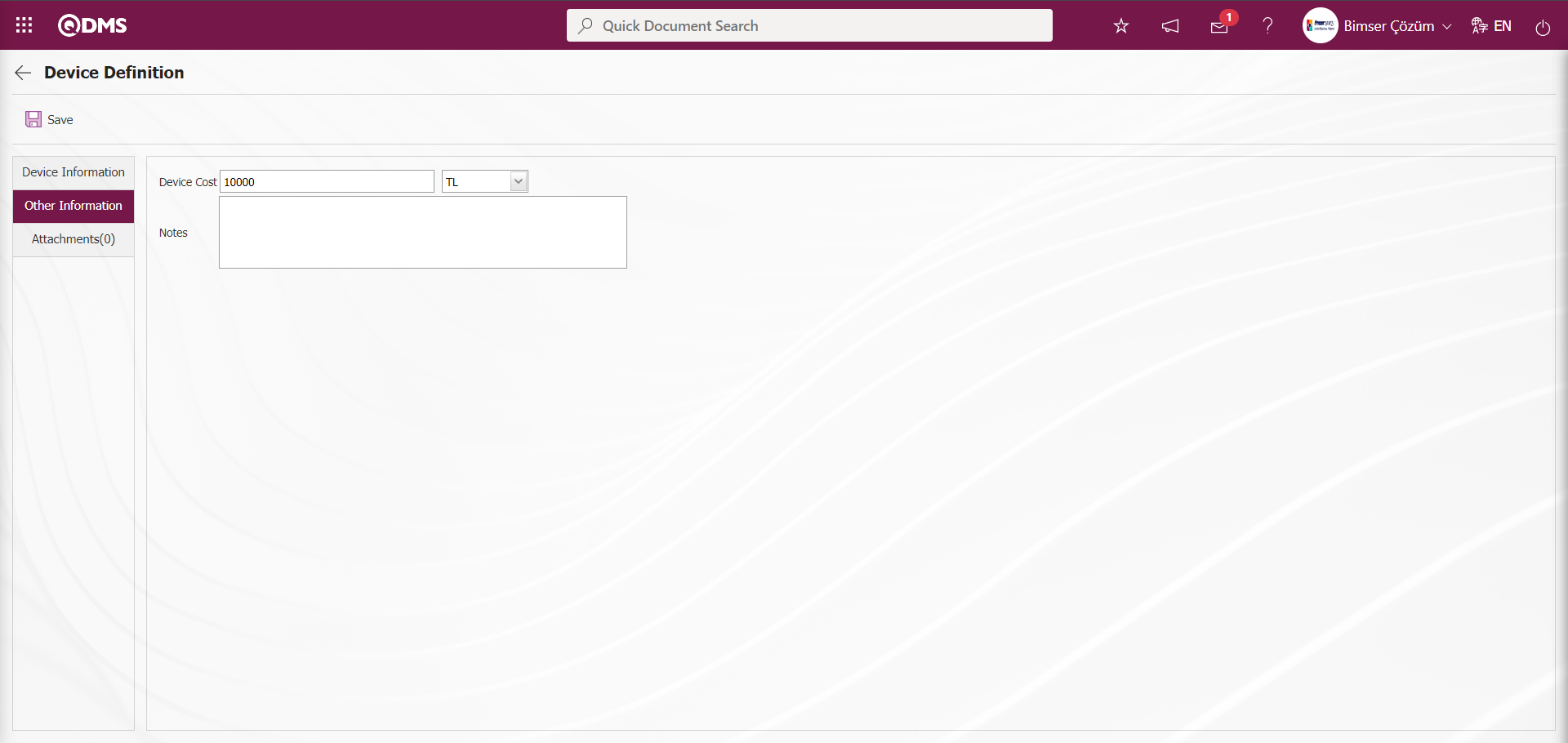
On the screen that opens, the relevant fields that come automatically are defined:
Device Cost: It is the field where the cost information of the device defined in the Other Information tab on the Device Definition screen is written and the unit is selected in the drop-down unit list.
Notes: This is the field where detailed notes, if any, about the device defined in the Device Information tab on the Device Definition screen are written.
Attachments tab: It is the tab where additional files such as documents, pictures, invoices, etc. are added.
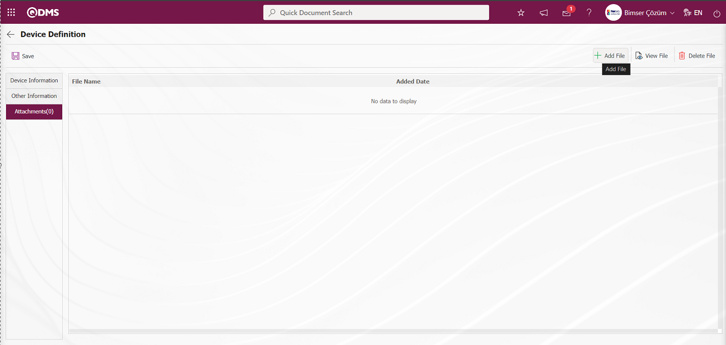
With the help of the buttons on the screen;
 : Additional file upload operation is done.
 : Viewing the additional file added to the list is done.
 : Delete the attachment file added to the list.
To add a new Attachment File to the Device Definition screen Attachments tab, click the button.
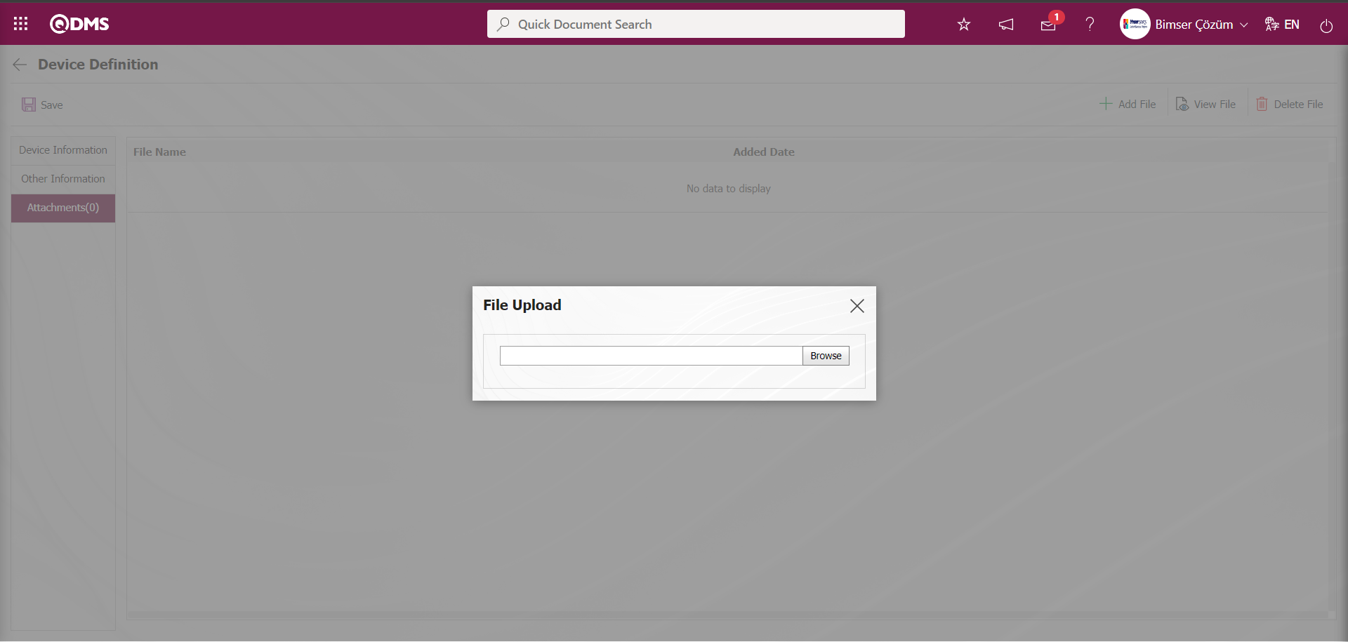
Click the  button on the File Upload screen.
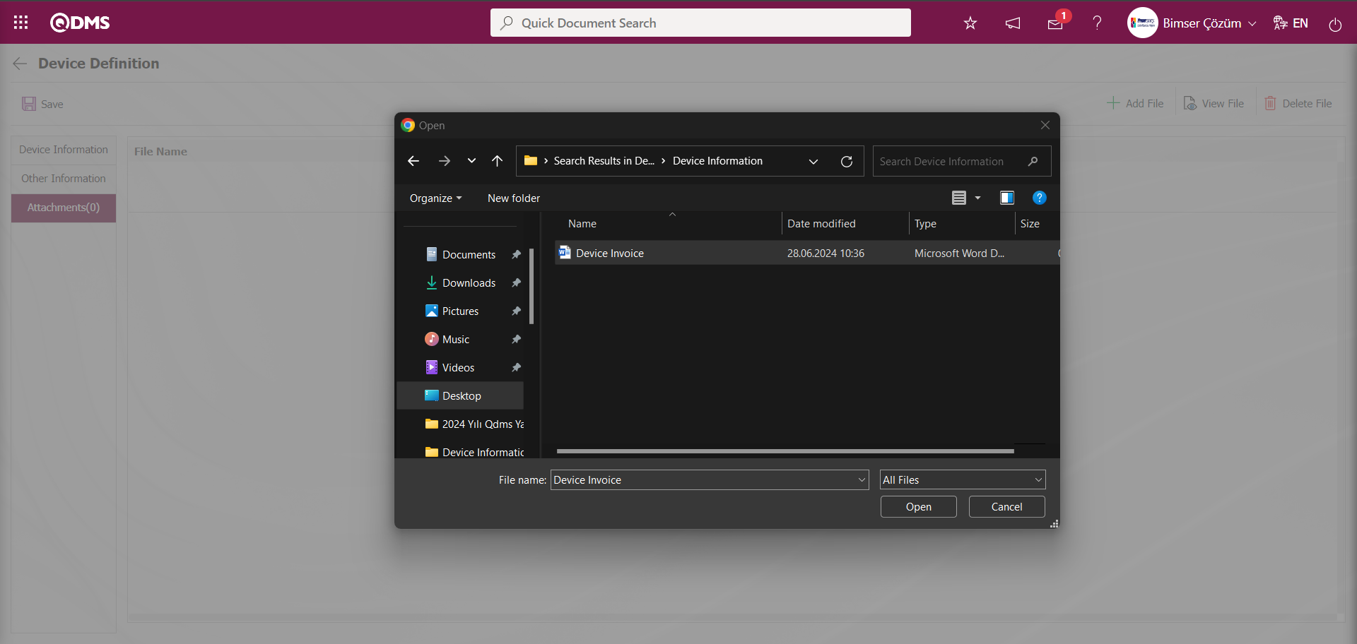
On the screen that opens, the Additional File to be uploaded to the system is selected and uploaded. 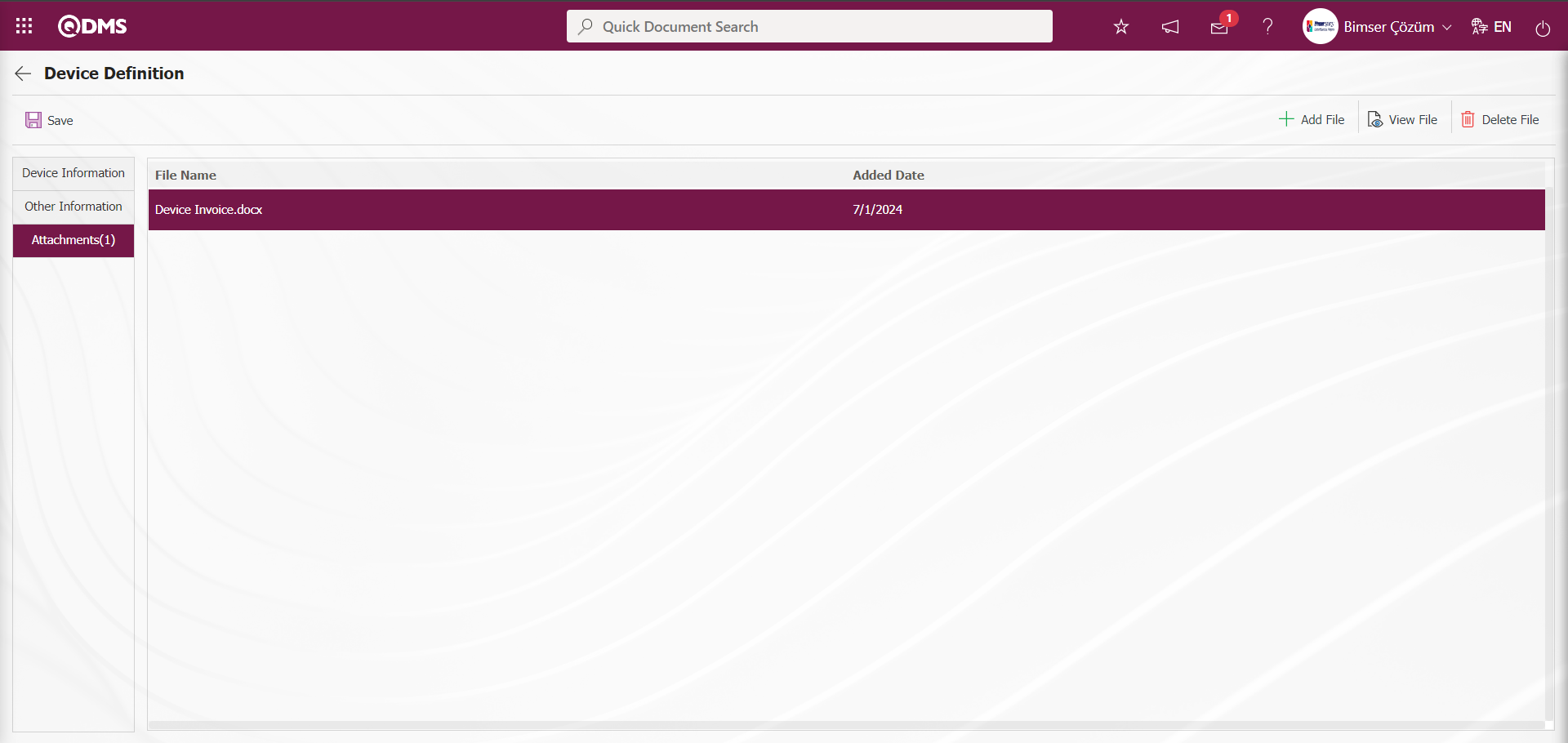
Click the Device Information tab.
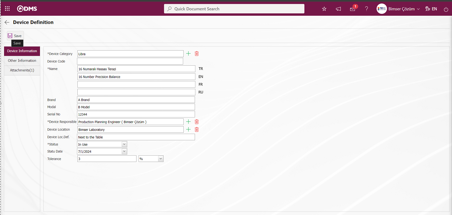
After entering all the necessary field information, the Device Identification registration process is performed by clicking the  button in the upper left corner of the screen. The identified Device is displayed in green color in the list tab on the Device list screen because its status is in use.
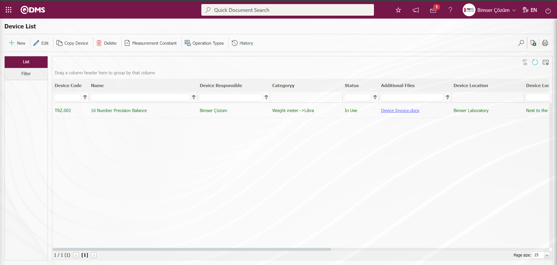
Defining Measurement Constants on Device Basis: If the  button is clicked while the defined device is selected, the screen where the measurement constants of the selected device will be entered is displayed. Defining measurement constants on device basis is done. In the Measurement Constants screen, if there are measurement constants previously defined for the device, they can be viewed, updated, deleted, new measurement constants can be defined if desired and the unit of measurement can be determined.
On the Device Definition screen, on the List tab, click the button while the device is selected in the list.
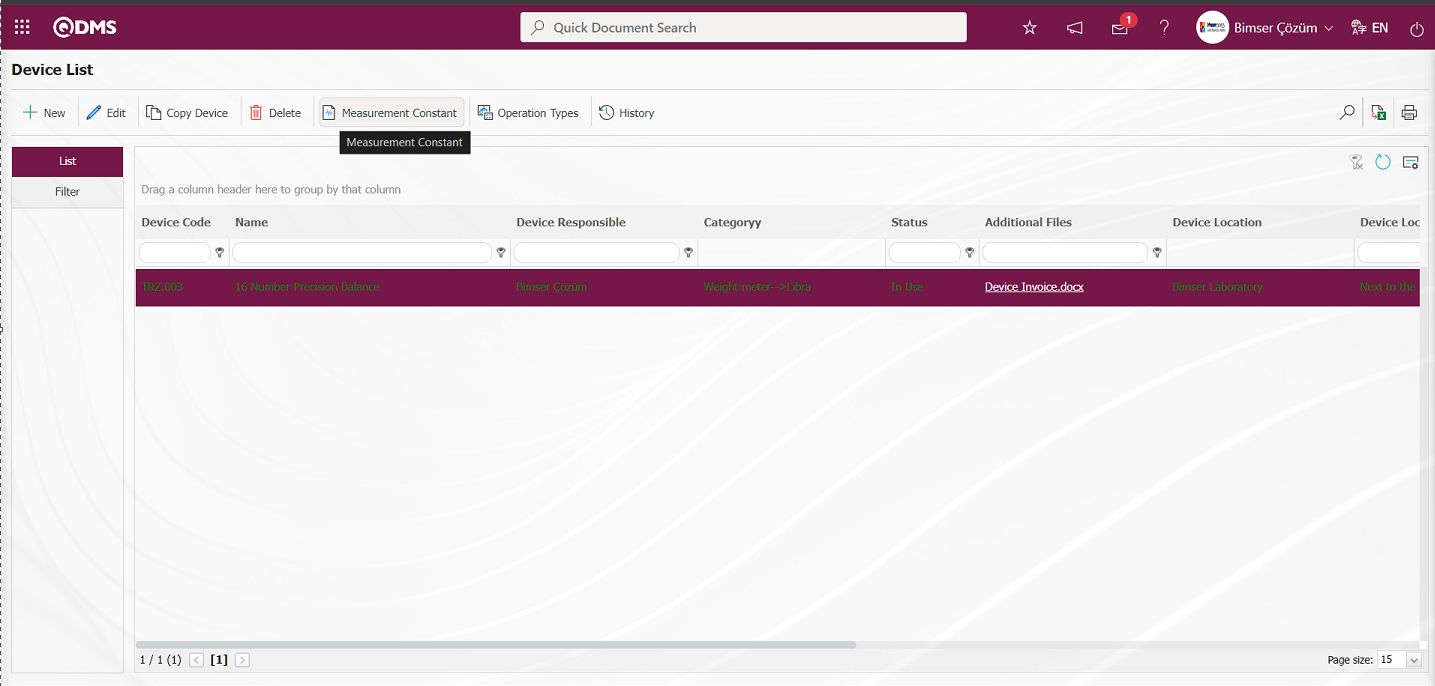
The Measure Constants screen opens.
With the help of the buttons on the screen;
 : Defining a new measurement constant is done.
: Edit and update the selected measurement constant information in the list.
 : Delete the selected measurement constant information in the list.
 : Defining a measurement unit is done.
: Return to the previous screen.
: Data can be exported to Excel.
: The search criteria on the menu screens are used to clean the data remaining in the filter fields in the grid where the search operation is performed.
: The menu screen is restored to its default settings.
: User-based designing is done on the menu screen with the show-hide feature, that is, the hiding feature of the fields corresponding to the columns on the menu screens.
To add new measurement constants to the list, click the  button at the top left corner of the screen to display the Measure Constants screen.
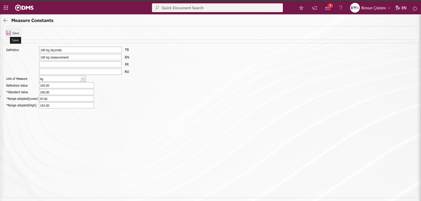
Related fields are defined on the screen that opens:
Definition: This is the field where the definition information of the measurement constant defined in the Measurement Constants screen is written.
Unit of Measurement: This is the field where the unit information of the measurement constant defined in the Measurement Constants screen comes to the System Infrastructure Definitions/BSID/ Definitions/ Unit of Measurement Definition menu. The defined units of measurement in this menu appear. If you want to define a new measurement unit, it should be defined from this menu. For example Pieces, Kilograms
Reference Value: This is the field where the reference value information of the measurement constant defined in the Measurement Constants screen is written.
Standard Value: This is the field where the standard value information of the measurement constant defined in the Measurement Constants screen is written.
Range adopted(Lower) : This is the field where the system calculates the range of acceptance sub information of the measurement constant defined in the Measurement Constants screen. Acceptance Range Lower information is automatically calculated by the system according to the tolerance value of the device 3%.
Range adopted(High): This is the field where the upper acceptance range of the measurement constant defined in the Measurement Constants screen is calculated by the system. Acceptance Range Upper information is calculated automatically by the system according to the tolerance value of the device 3%.
Enter the definition information of the measurement constant. The unit of measurement of the measurement constant is selected from the options defined in the system. Reference and standard value information is entered. Acceptance range lower and acceptance range upper information is calculated automatically by the system according to the tolerance value given in the device category definition screen. After the required fields are filled in, the  button in the upper left corner of the screen is clicked and the measurement constants definition registration process is performed.
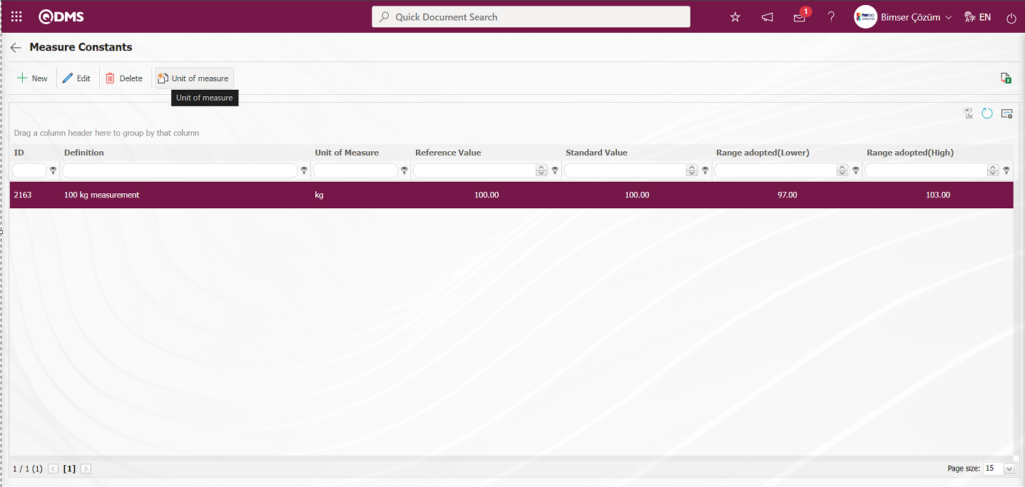
Any number of measurement constants can be defined for a device. The units of measurement can be defined with the  button on the measurement constants screen. When the button is clicked and the new measurement unit definition screen is displayed, the units for the measurement constants are defined.
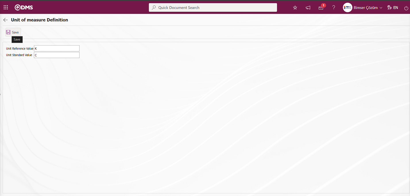
Related fields are defined on the screen that opens:
Unit Reference Value: This is the field where the reference value unit information is written in the Unit of measure Definition screen.
Unit Standard Value: This is the field where the standard value unit information is written in the Unit of measure Definition screen.
For the reference and standard measurement constants on the Unit of measure Definition screen, the reference and standard measurement units are written and the unit of measure definition registration process is done by clicking the button in the upper left corner of the screen.
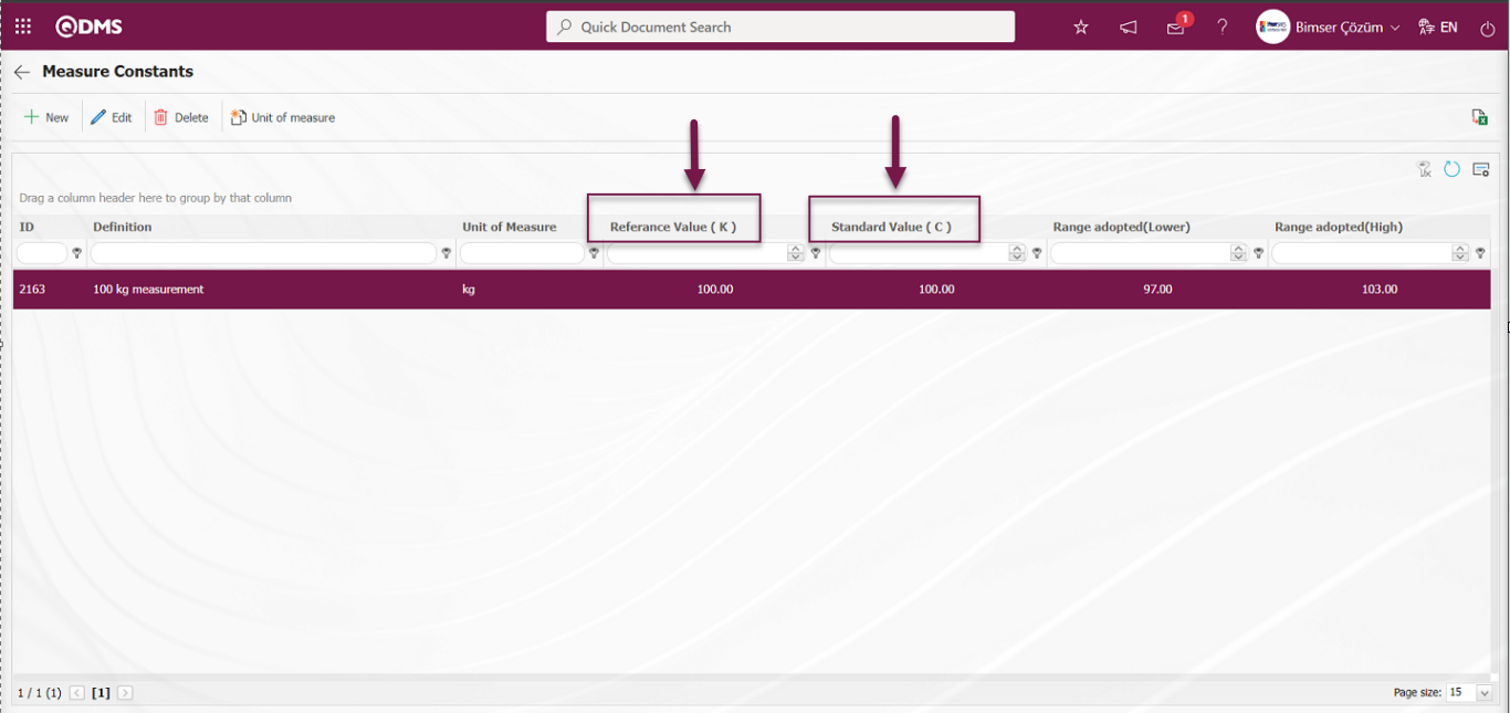
Defining Operation Type on Device Basis: If the  button is clicked while the defined device is selected, the operation type screen will be displayed where the operation type of the selected device will be assigned. Defining the operation type on device basis is done. If there is a operation type previously defined for the device on the operation type screen of the device opened, it can be displayed, updated, deleted, and a new operation type can be defined if desired. Click the button to assign one or more of the operation types defined in the list on the device list screen to the selected device.
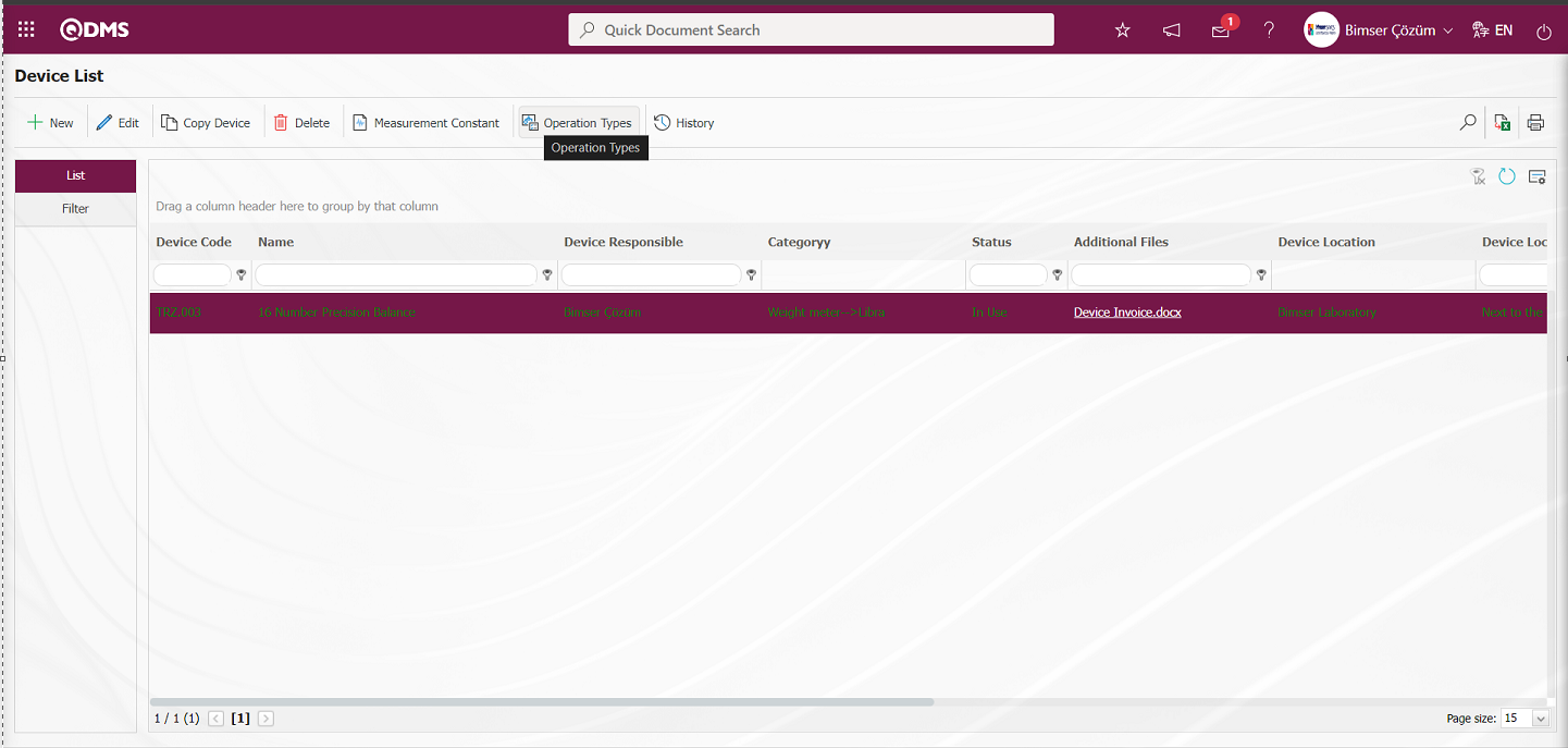
The Operation Types in Device screen opens.
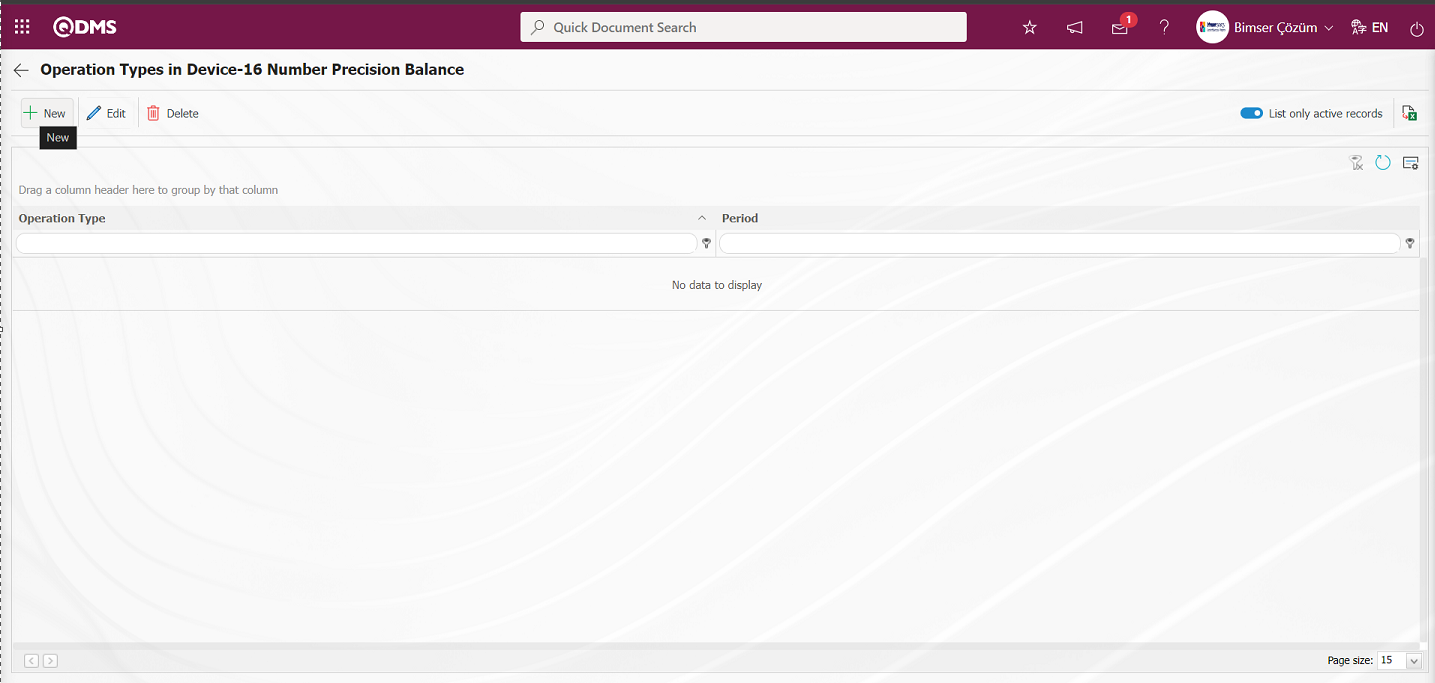
With the help of the buttons on the screen;
: Defining the operation type of a new device is done.
: Changes and updates are made on the operation types information of the device selected in the list.
: Delete the operation type information of the device selected in the list
 : Returns to the previous screen.
 : Data can be exported to Excel.
: The search criteria on the menu screens are used to clean the data remaining in the filter fields in the grid where the search operation is performed.
: The menu screen is restored to its default settings.
: User-based designing is done on the menu screen with the show-hide feature, that is, the hiding feature of the fields corresponding to the columns on the menu screens.
To add a new device sub-operation type to the list, click the button at the top left corner of the screen to display the Device Operation Types screen.
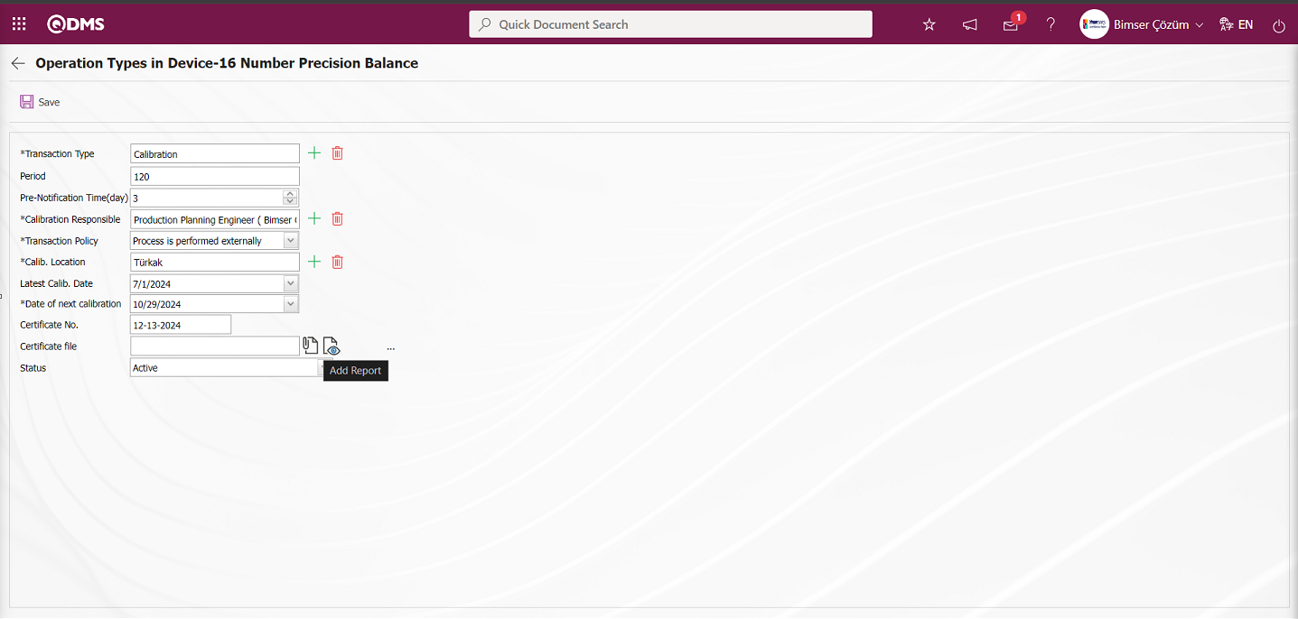
On the Operation Types in Device screen, the certificate file of the device is added by clicking the  (Add Report) button.

Click the  button on the File Upload screen.
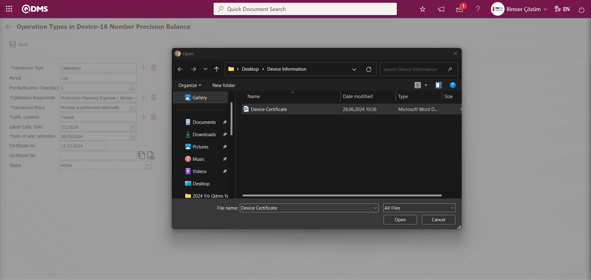
Select the Certificate File to be added on the screen that opens and add it.
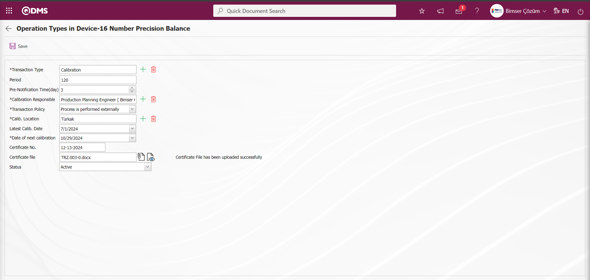
“Certificate File has been uploaded successfully” message is given by the system to indicate that the certificate file has been added.
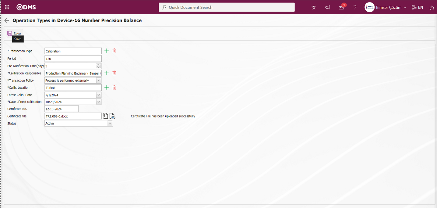
Related fields are defined on the screen that opens:
Transaction Type: This is the field where the transaction type of the device is selected from the list of transaction types defined in the system opened by clicking the  (Select) button on the Operation Types in Device screen. Operation Type list comes as defined in the System Infrastructure Definitions / Device Management / Operation Types Definition menu.
Period: It is the field where the period information of the operation types of the device defined on the Operation Types in Device screen is written. Calibration period definition is made on the basis of day and month according to the value written in the parameter value in the parameter number 10 in the Device Management System Module parameters.
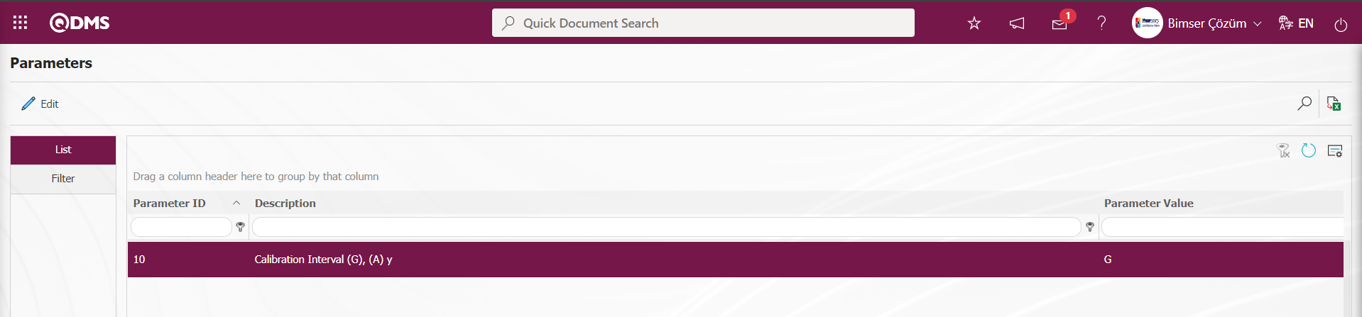
To set the calibration period on day basis, the letter “G” is written to the parameter value in parameter number 10. If you want to set the calibration period on a month basis, the letter “A” is written to the parameter value in parameter 10. According to this adjustment made in the parameter, the value is entered in this field on a day and month basis.
Pre-notification Period (days): This is the field where the pre-notification period information is written in days on the Operation Types in Device screen. It is determined how many days in advance of the type of operation to be performed for the device.
Calibration Responsible: This field is selected from the list of positions defined in the system opened by clicking the Operation Responsible  (Select) button on the Operation Types in Device screen.
Transaction Policy: Operation Types in Device screen, the drop-down list can be selected from the list of operation policies by clicking on the drop-down list. Selectable Operation Policies; “Process is performed internally”, “Process is performed externally”, “Process is performed internally and externally” and “Process cannot be tracked periodically”.
Calib. Location: It is a field displayed on the Operation Types in Device screen on the list tab depending on the operation policy options.When the “Process is performed internally” option is selected, a selection is made from the company profile list defined in the system by clicking the (Select) button. When the “Process is performed externally” option is selected, a selection is made from the list of processing locations defined in the system by clicking the (Select) button. When the “Process is performed internally and externally” option is selected, select from the company profile list defined in the system opened by clicking the (Select) button. When the “Process cannot be tracked periodically” option is selected, select from the company profile list defined in the system opened by clicking the (Select) button.
Last Calibration Date: It is the field where the last operation date information of the operation types of the device on the Operation Types in Device screen is selected in the calendar field.
Date of next calibration: It is the field where the future operation date information of the operation types belonging to the device on the Operation Types in Device screen is automatically calculated by the system according to the period information based on the last operation date.
Certificate No: This is the field where the certificate number information of the operation types of the device on the Operation Types in Device screen is written.
Certificate File: This is the area where the certificate file of the operation types of the device on the Operation Types in Device screen is added from the system and the display of the added certificate file is done with the help of buttons.
(Add Report): The certificate file of the device is uploaded to the system.
 (View Report): The certificate file of the installed device is viewed.
Status: This is the field where Operation Types in Device passive or active status information is selected.
Select one of the predefined operations on the Operation Types in Device screen. Enter the period, pre-notification period, calibration responsible, operation location, operation policy, last operation date information of the operation type. The system automatically calculates the next transaction date according to the period information. It can also open the next work order automatically on this date if the parameter is activated. Different types of transaction types can be added to a device. After the required fields are filled in, the button in the upper left corner of the screen is clicked and the Defining Operation Types for the Device registration process is realized.
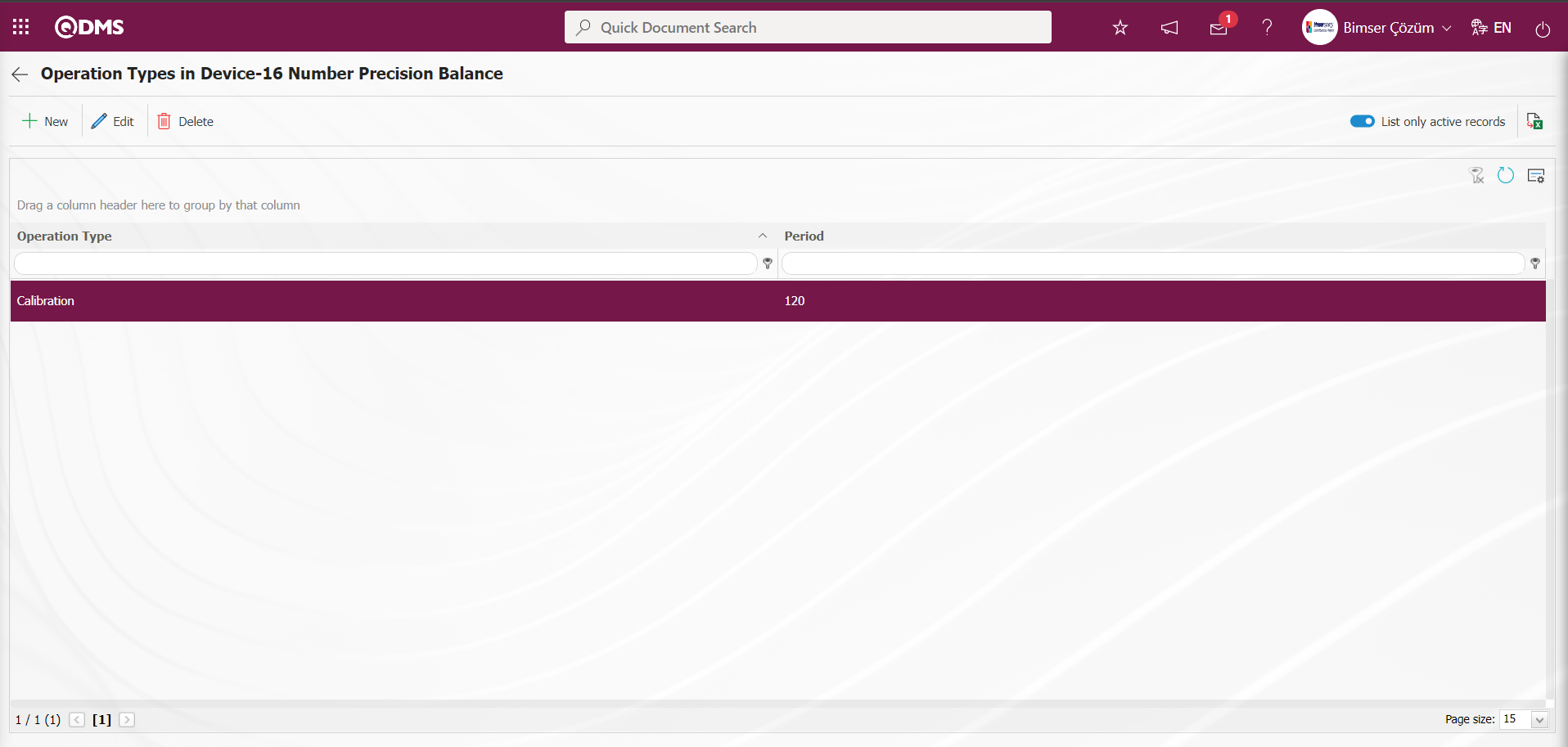
Calibration History:On the device list screen, the operation history information of the device is displayed by clicking the selected  button from the list tab on the list.
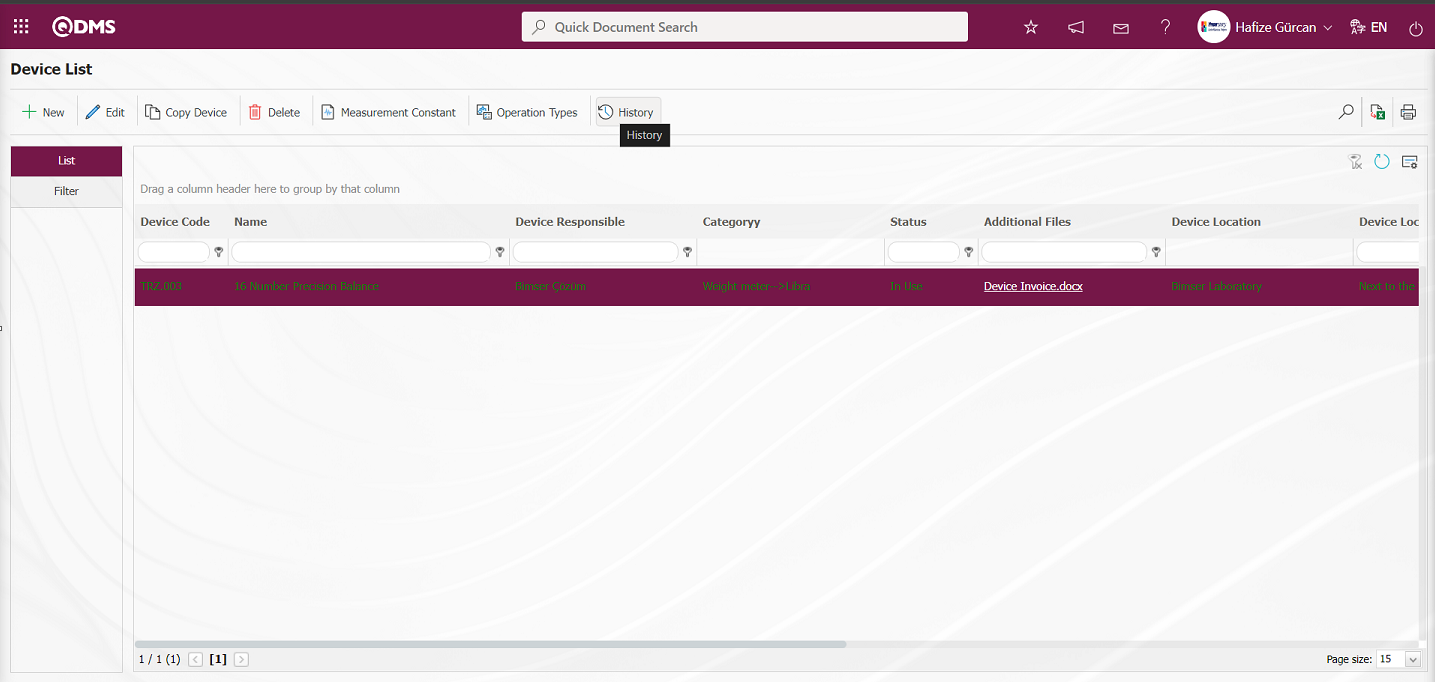
While the device is selected on the device list screen, click the button.

In the Calibration History screen, the operation type is selected and the operation history is displayed by clicking the  button.
In the History tab: Device and process history information is displayed.
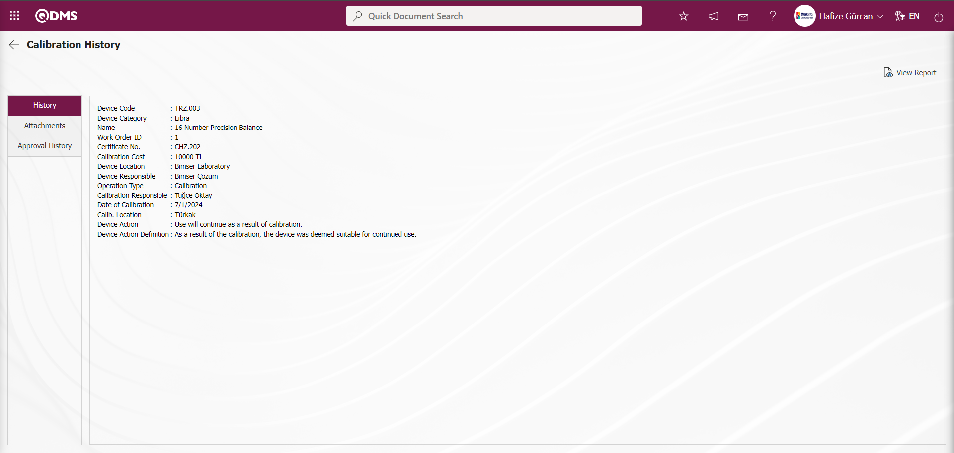
With the help of the buttons on the screen;
 : Calibration Report is displayed
Attachments tab:Additional files, if any, attached to the device are displayed.

With the help of the buttons on the screen;
 : The information of the file selected in the list is displayed.
Approval History tab: Approval history information such as the name and surname of those who approved the device, approval date and status are displayed.
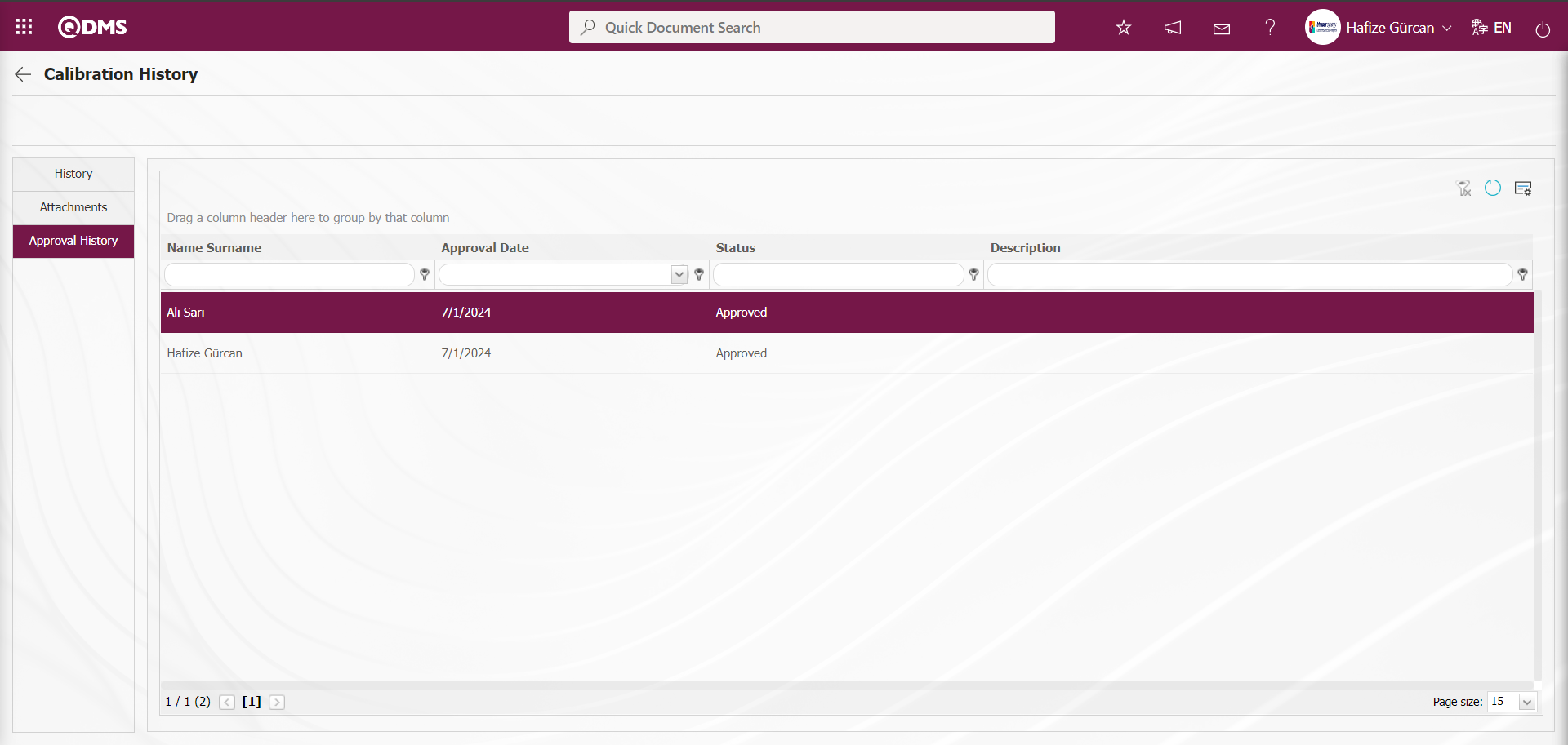
6.2.2. Fulfill operation
Menu Name: Integrated Management System/ Device Management System/ Fulfill operation
It is the menu where the process of manually opening work orders and performing automatically opened work orders is performed. The parameter is activated by selecting the parameter value “Yes” of the parameter 26 “When work orders automatically openm the day” from the Device Management Module parameters.
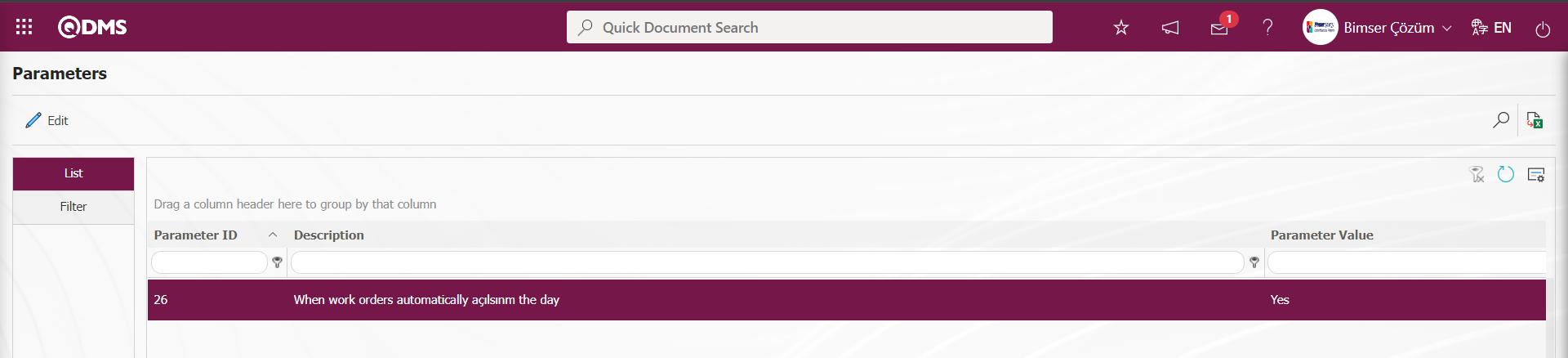
After the parameter is activated, all work orders will be opened automatically on time. However, it is also possible to open a work order manually to perform an operation ahead of time. To open work orders manually and to execute automatically opened work orders, click on the Fulfill operation menu under the Integrated Management System menu of the Device Management Module.
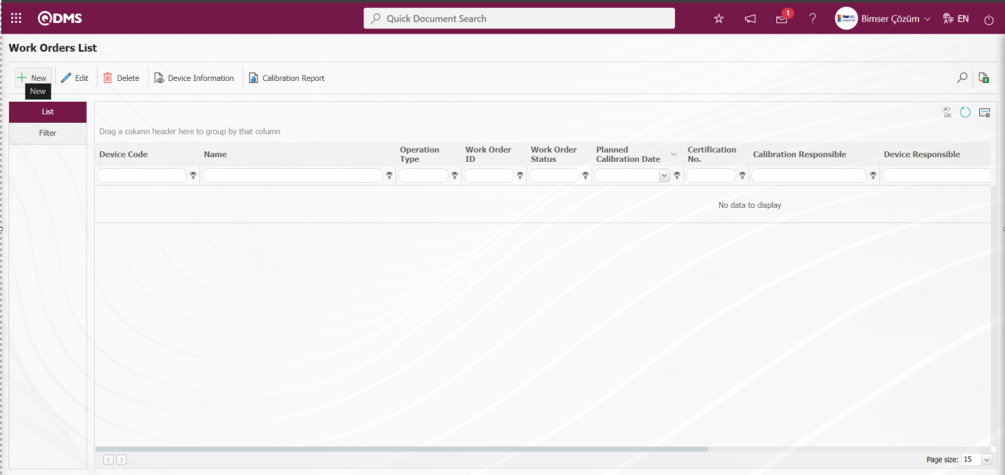
With the help of the buttons on the screen;
 : Defining a new work order is done.
: Updating and editing the work order information selected in the list is done.
: Delete the work order information selected in the list.
 : Device information screen is opened and device information is displayed.
 : Calibration report is taken.
 : Filtering is done between work orders according to the specified filters.
 : Data is transferred to Excel.
: The search criteria on the menu screens are used to clean the data remaining in the filter fields in the grid where the search operation is performed.
: The menu screen is restored to its default settings.
: User-based designing is done on the menu screen with the show-hide feature, that is, the hiding feature of the fields corresponding to the columns on the menu screens.
To add a new work order to the list, click the button in the upper left corner of the screen to open the Work Order List screen.
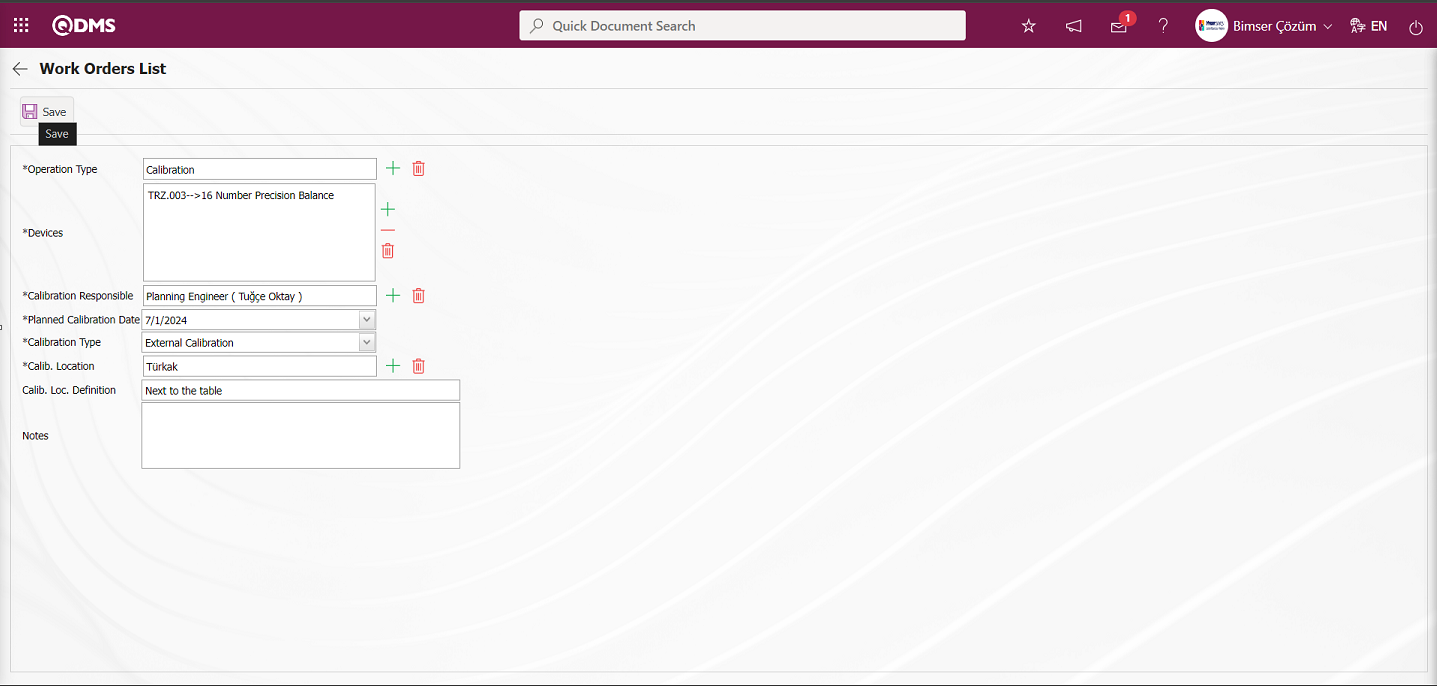
Related fields are defined on the screen that opens:
Operation Type: This is the field where the operation type information is selected in the operation type list defined in the system opened by clicking the  (Select) button on the Work Order List screen.
Devices: This is the field where the devices to be processed are selected from the list of devices to be processed opened by clicking the (Select) button on the Work Order List screen. The list of the selected devices to be processed comes depending on the type of operation selected in the operation type field. According to the operation type defined for the device, the list of devices to be processed is displayed and selection is made. Devices for which the selected operation type is not defined are included in the list
Calibration Responsible: This is the field where the process responsible of the device is selected from the list of positions defined in the system opened by clicking the (Select) button on the Work Order List screen. The person responsible for calibration is the staff member who performs the calibration, verification, or maintenance of the device.
Planned Calibration Date: This is the field where the planned calibration date of the device is selected in the calendar field opened on the Work Order List screen.
CalibrationType: This is the field where the processing location type of the device is selected from the options opened by clicking the drop-down list on the Work Order List screen. Calibration type information is selected depending on two options, internal and external.
Calib. Location : This is the field where the Calib. Location information of the device is selected on the Work Order List screen. Calib. Location information of the device differs depending on the option in the processing location type field. When Calib. Location Type internal option is selected, company profile list is displayed. By clicking the (Select) button in the Calib. Location field of the device, a selection is made in the company profile list defined in the system. Company Profile list is defined in System Infrastructure Definitions/BSID/Definitions/Company Profile list. When the Calib. Location Type external option is selected, the list of processing locations is displayed. By clicking the (Select) button in the Process Location field of the device, a selection is made in the list of process locations defined in the system. The list of processing locations is defined in System Infrastructure Definitions/Device Management System/Processing Locations list. The parameter value of parameter 47 of the Device Management System parameters is activated by selecting “Yes”.
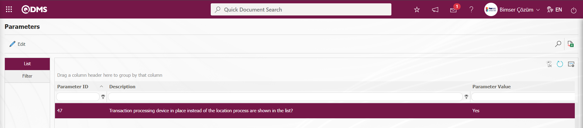
After the parameter is activated, it is shown in the trade execution list as device location instead of trade location.
Calib. Loc. Definition: This is the field where the processing location description information of the device is written on the Work Order List screen
Notes: This is the field where detailed notes about the device are written on the Work Order List screen.
On the Work Order List screen, select the transaction type information in the transaction type field. Depending on the operation type selected in the Devices to be processed field, the list of devices to be processed is displayed and the selection of the devices to be processed in this device list is made. The calibration responsible of the device is selected in the system defined position list opened by clicking the (Select) button. The calibration location type of the device is selected as internal and external in the drop-down list. Depending on the calibration location type external option, the list of operation locations defined in the system is displayed in the operation location field and the calibration location information of the device is selected in the displayed operation locations list. The description of the processing location of the device and note information about the device is written. After entering the relevant information in the required fields, the work order registration process is done by clicking the  button in the upper left corner of the screen. After the work order registration process, it is assigned to the person who is responsible for the process.
According to the value defined in the parameter value in parameter 16 of the Device Management System module parameters, the authorization to make transactions from work orders is given. Since the “I” value is defined in the parameter value, the transaction is authorized to make transactions in the responsible work orders.
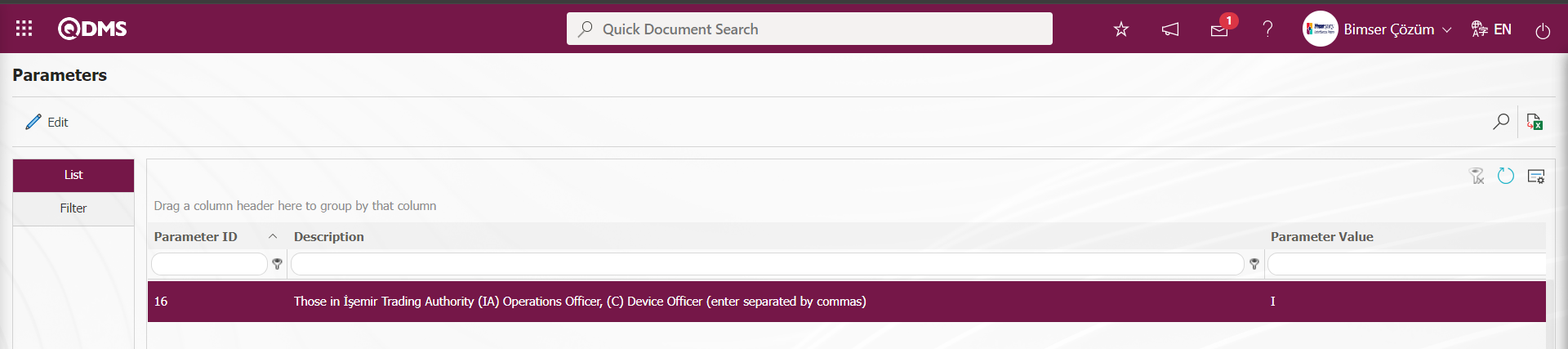
Depending on this parameter, if desired, the authorization to make transactions in work orders is given to the device responsible. In order to authorize the device supervisor to make transactions in work orders, it is necessary to define the parameter value as “C” in the parameter.
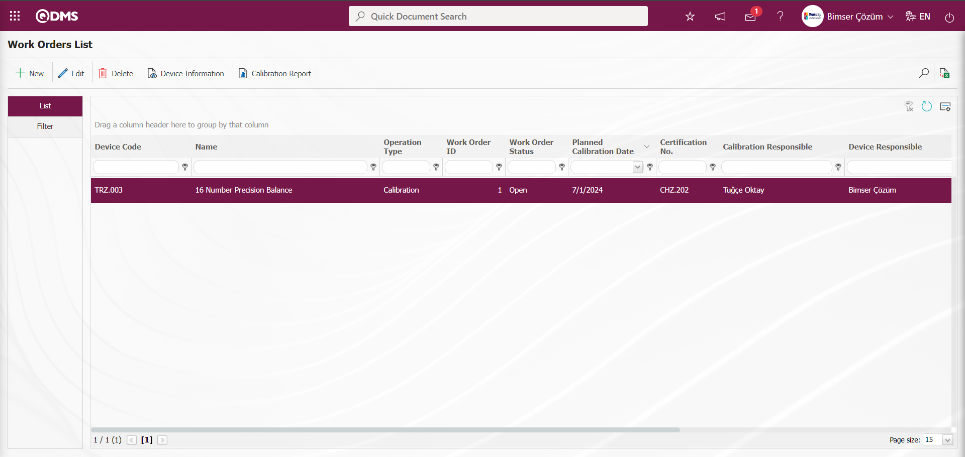
The device responsible person has the task“Processing Devices Under My Responsibility” on the “My Pending Jobs” page.
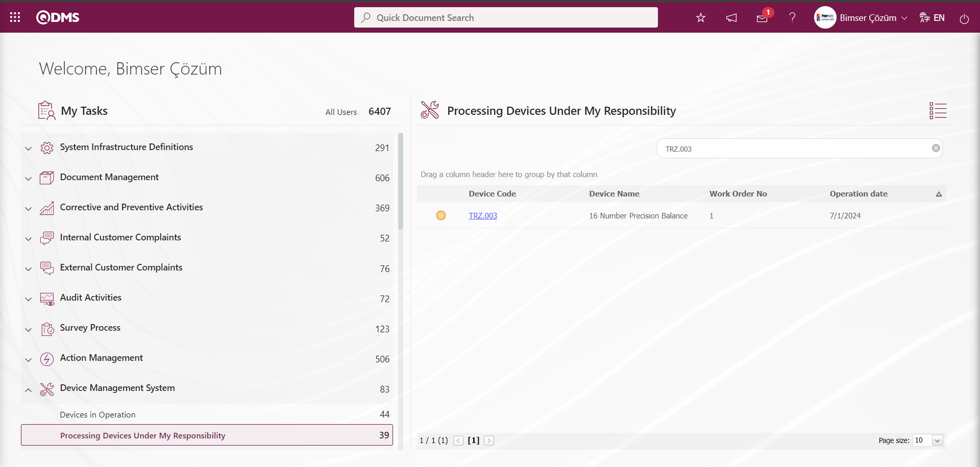
The Device Responsible opens the Job Order list screen by clicking the link in the Device code field in the relevant task.

With the help of the buttons on the screen;
 : New work order is defined.
: The work order information selected in the list is updated and edited.
: The work order information selected in the list is deleted.
: The device information screen opens to display device information.
: The process of receiving the calibration report is done.
: Work orders are filtered according to the specified filters.
: Data is exported to Excel.
: The search criteria on the menu screens are used to clean the data remaining in the filter fields in the grid where the search operation is performed.
: The menu screen is restored to its default settings.
: User-based designing is done on the menu screen with the show-hide feature, that is, the hiding feature of the fields corresponding to the columns on the menu screens.
The Device Responsible performs the work order by clicking the  button while the work order is selected in the Work Orders List.
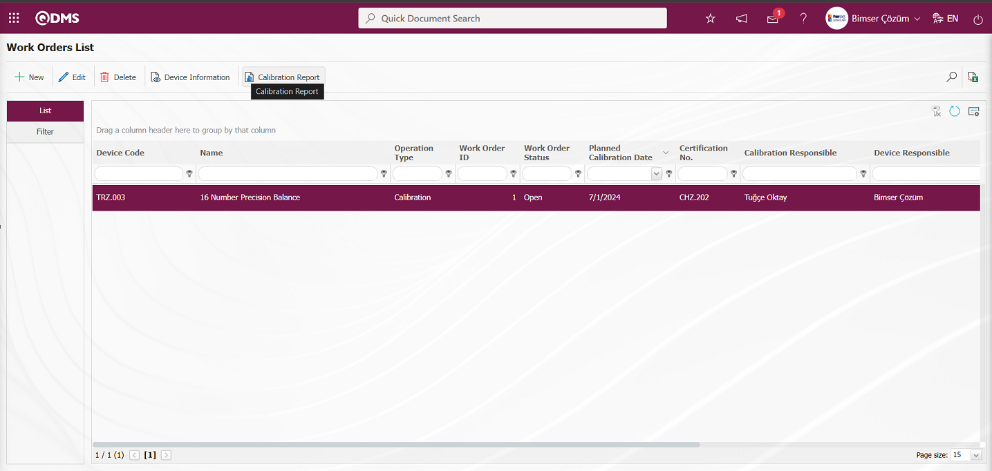
On the Calibration Report screen, select the Device Action field. In the relevant section of the report operations, prepare and view the report, close the work order, close the work order and publish
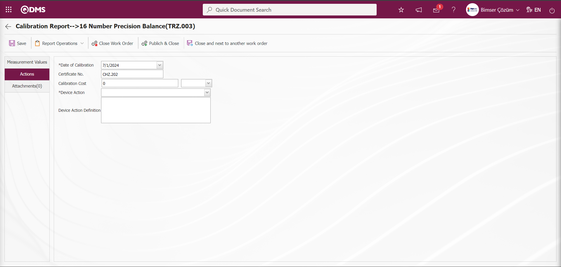
A reminder e-mail will be sent to the device responsible and the process responsible according to what is done inside according to the value defined in parameter 25 in the Device Management System parameters until the number of days specified in the parameters when the process time is approaching. 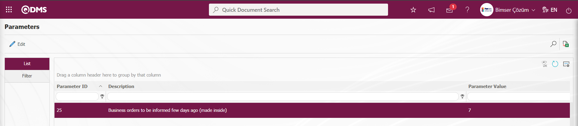
A reminder e-mail will be sent to the device responsible and the transaction responsible according to the value defined in parameter 27 in the Device Management System parameters according to the value defined in parameter 27 in the Device Management System parameters until the number of days specified in the parameters when the transaction time is approaching.
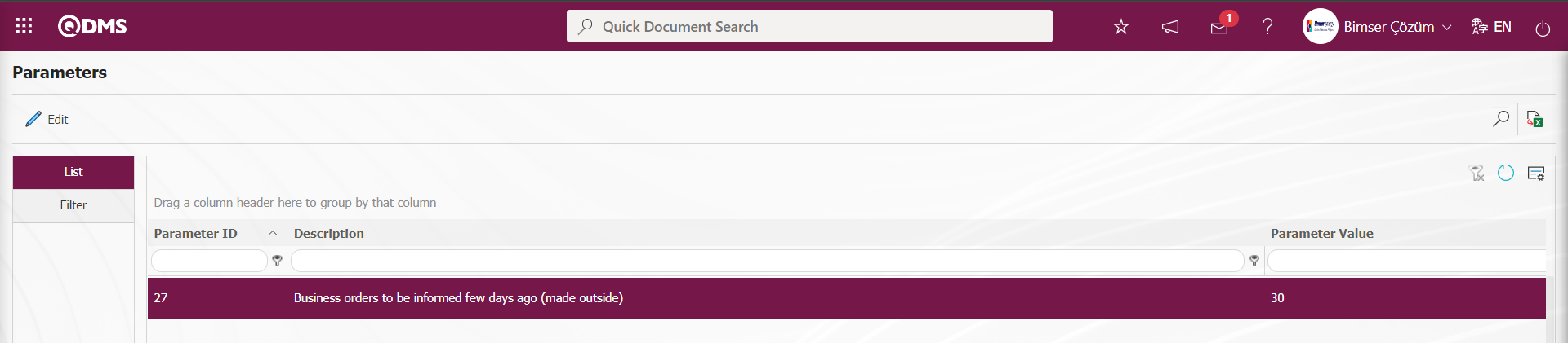
A job is created as “Devices in Operation” task from the“My Pending Jobs” page of the process supervisor. This work order must be executed until the scheduled completion date, otherwise delay mails will start to be sent. On the “My Pending Jobs” screen, the delayed jobs are displayed in red, and the jobs that have not yet reached the planned end date are displayed in yellow. From the Qdms main login screen, the user name and password information of the Process Supervisor is entered.

Login to the Operation Responsible's Qdms local address. From the “My Pending Jobs” page of the Operation Responsible, a job is created as the“Devices in Operation” task .
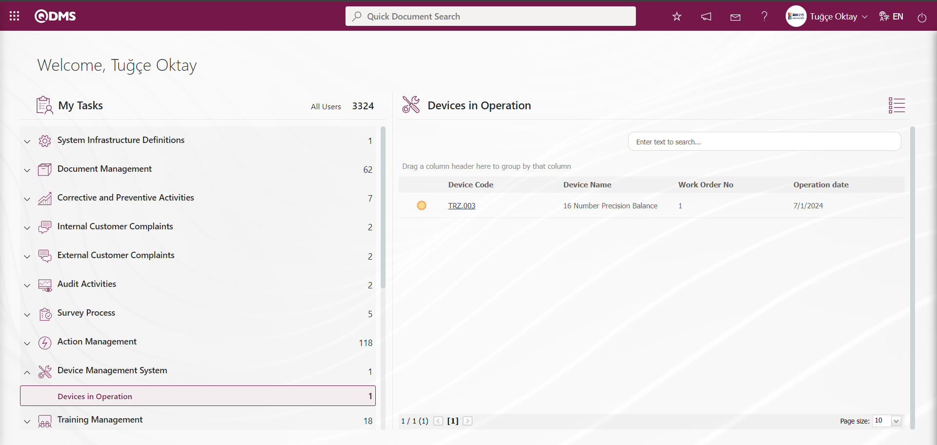
The process responsible opens the Work order list screen by clicking the link in the Device code field in the relevant task.

With the help of the buttons on the screen;
: New work order is defined.
: The work order information selected in the list is updated and edited.
: The work order information selected in the list is deleted.
: The device information screen opens to display device information.
: The process of receiving the calibration report is done.
: Work orders are filtered according to the specified filters.
: Data is exported to Excel.
: The search criteria on the menu screens are used to clean the data remaining in the filter fields in the grid where the search operation is performed.
: The menu screen is restored to its default settings.
: User-based designing is done on the menu screen with the show-hide feature, that is, the hiding feature of the fields corresponding to the columns on the menu screens.
On the work orders list screen, while the work order is selected in the list, press the  button and select the work order.
This page consists of 3 tabs; Measurement Values, Actions and Attachments.
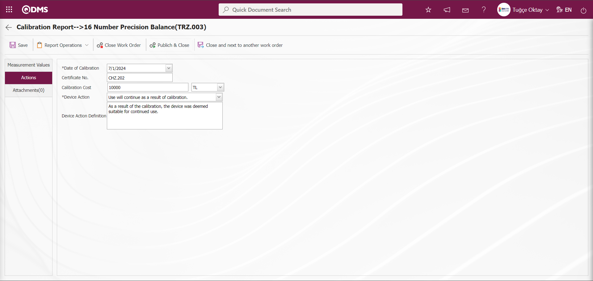
With the help of the buttons on the screen;
 : Saving the reports as they exist is done.
 : Operations related to the report operations of the work order selected in the list are performed. These operations are preparing and uploading the calibration report.
 : Calibration Report is prepared.
 : Manual upload of the process report is done. (Optional)
 : The work order is closed.
 : The work order is published and closed.
 : The work order is closed and the next work order is started.
  : Returns to the previous page.
Measurement Values Tab: This is the tab where defined measurement values related to the device can be displayed, new measurement values can be defined, defined measurement values can be updated and deleted.
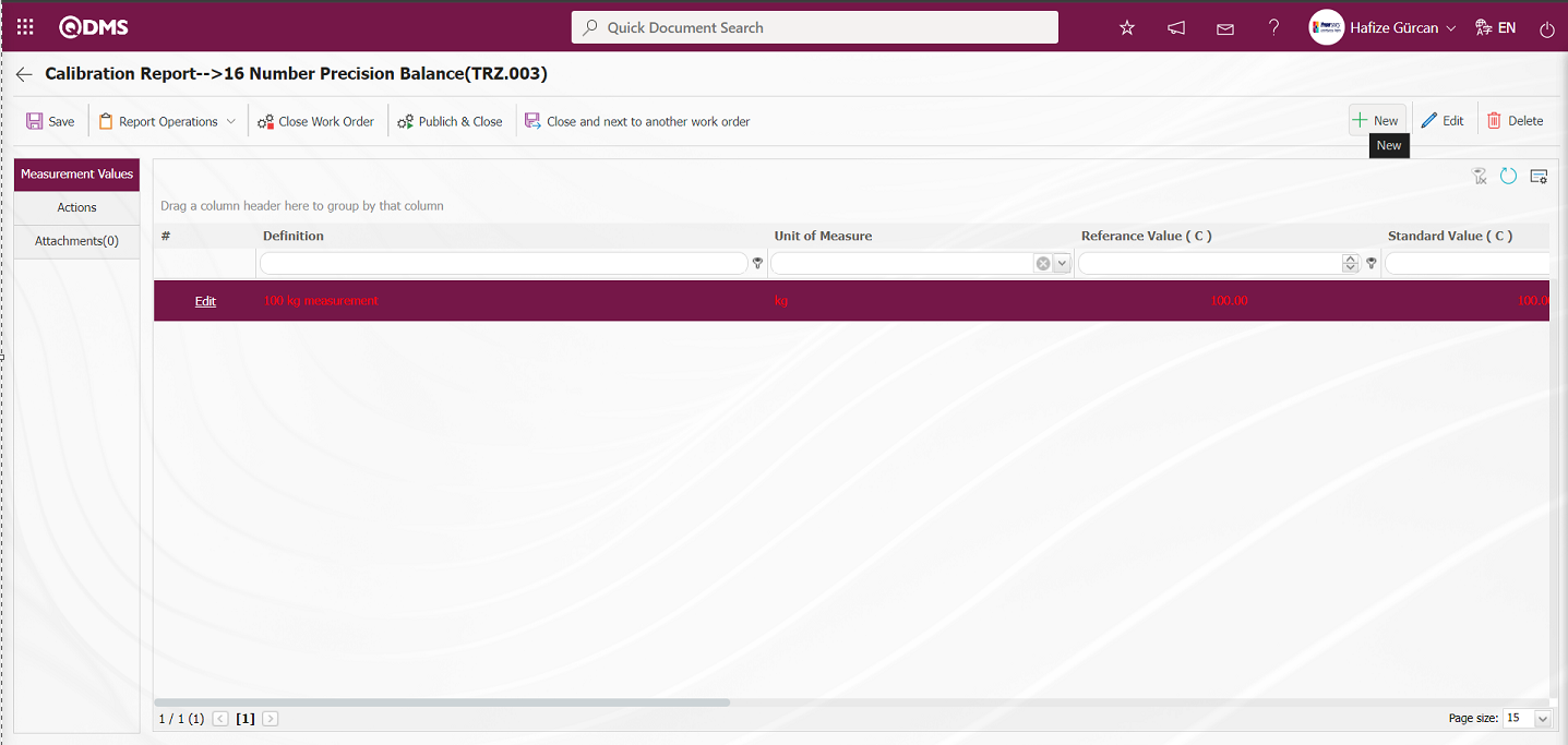
With the help of the buttons on the screen;
: A new measurement constant is defined.
: Edit and update the selected measurement constant information in the list.
: Delete the selected measurement constant information in the list.
: Return to the previous screen.
: Data can be exported to Excel.
: The search criteria on the menu screens are used to clean the data remaining in the filter fields in the grid where the search operation is performed.
: The menu screen is restored to its default settings.
: User-based designing is done on the menu screen with the show-hide feature, that is, the hiding feature of the fields corresponding to the columns on the menu screens.
To add new measurement constants to the list, the Measure Values screen is displayed by clicking the button in the upper left corner of the screen.
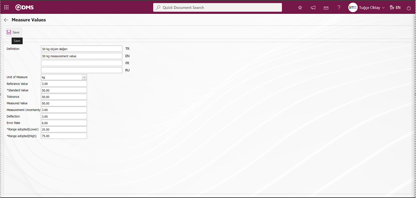
The relevant fields are defined on the screen that opens:
Definition: This field contains the definition information for the measurement value defined on the Measure Values screen.
Measurement Unit: This is the area where the unit information of the measurement value defined in the Measure Values screen is displayed in the System Infrastructure Definitions/BSID/Definitions/Measurement Unit Definition menu. The measurement unit defined in this menu is displayed. If you want to define a new measurement unit, you must do so in this menu. For example, Meter, Kilogram, etc.
Reference Value: The field where the reference value information of the measurement value defined in the Measure Values screen is entered.
Standard Value: The field where the standard value information of the measurement value defined in the Measure Values screen is entered.
Tolerance: The area where the tolerance information is entered and displayed.
Measure Value: The field where the measurement value defined in the Measure Values screen is written.
Measure Uncertainty: The field where the measurement uncertainty of the measurement value defined in the Measure Values screen is written.
Range adopted (Lower): This is the area where the system calculates the range adopted (lower) information for the measurement value defined in the Measure Values screen.
Range adopted (High): This is the area where the system calculates the range adopted (high) information for the measurement value defined in the Measure Values screen.
If previously defined measurement constants exist, the measurement value definition, measurement unit, reference value, standard value, adopted range (lower), and adopted range (high) are pre-filled. By entering only the measured value, the system calculates the deviation and error rate, and the values are saved by clicking the  button.

To change the selected measurement value in the list, click the  button.
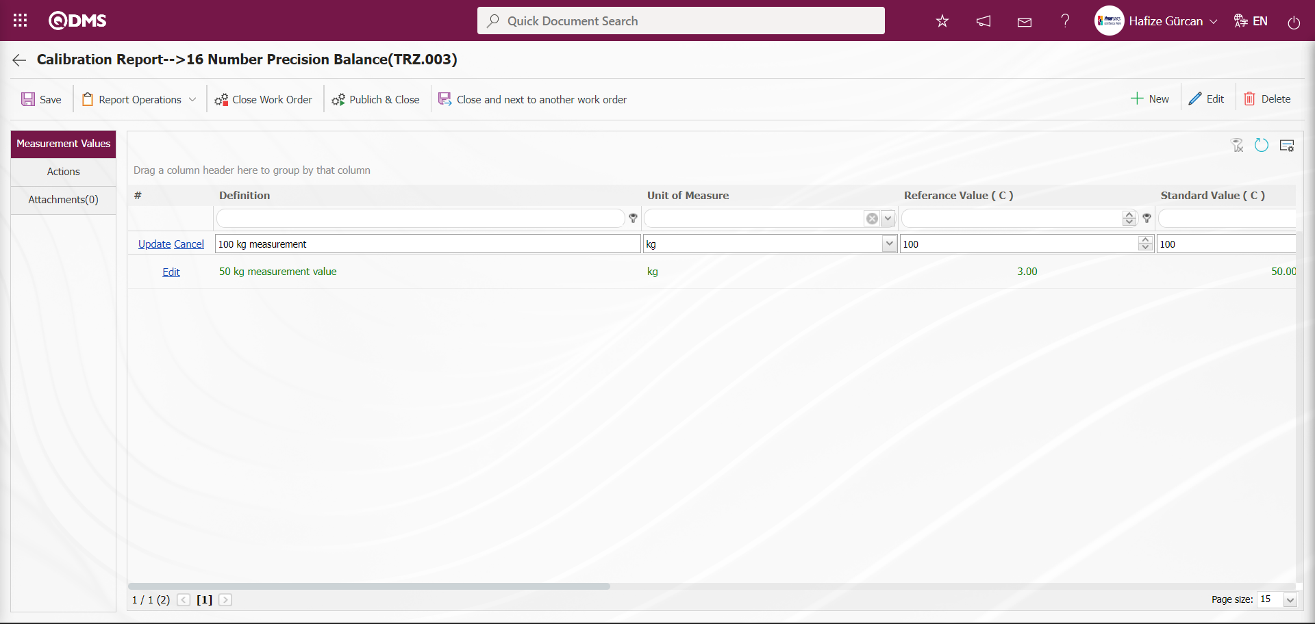
Measurement values are changed and adjusted. Measurement values displayed in green indicate that the measurement value is suitable for the device, while those displayed in red indicate that the measurement value is not suitable for the device.
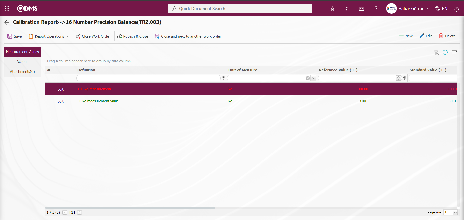
Actions Tab: This tab contains information such as the transaction date, certificate number, transaction cost, device action, and device action definition related to transactions performed on the device.
The relevant fields are defined on the screen that opens:
Calibration Date: This is the field where the device's calibration date is specified in the calendar field that opens in the actions tab of the Calibration Report screen.
Certificate No: This is the field where the device's certificate number is specified by the system in the actions tab of the Calibration Report screen.
Calibration Cost: The field where the device's calibration cost information is entered and the unit of measurement is selected in the calibration report screen under the Actions tab.
Device Action: The field where the device action information is selected in the calibration report screen under the Actions tab. This is a list of definitions made by clicking the  button while the action type is selected in the action type definition menu.
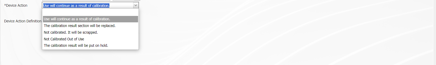
When the “Calibration result section will be changed” option is selected in the device-specific actions field, additional fields are displayed depending on this option. The additional fields are “New Location of the Device,” “New Location Definition, and ‘New Responsible .’ To display these fields, select the device-specific operation type in the operation type definition menu, click the button, check the box for the field to be changed, and then perform the result definition operation. When this option is selected, the relevant fields must be filled in.
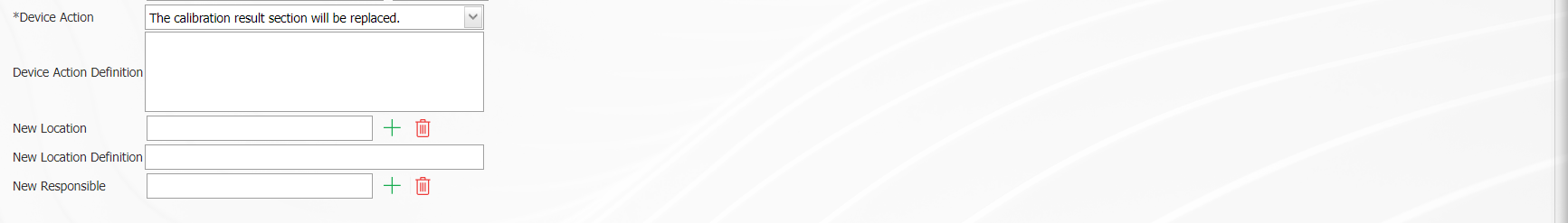
In this field, select the option “The calibration result section will be replaced.
Device Action Definition: This is the field where device action definition information is entered in the Operations tab of the Calibration Report screen.
Attachments Tab: This tab is where you upload any additional files, such as measurement reports, certificates, invoices, and images, related to the procedures performed on the device to be added at this stage of the Calibration Report screen.
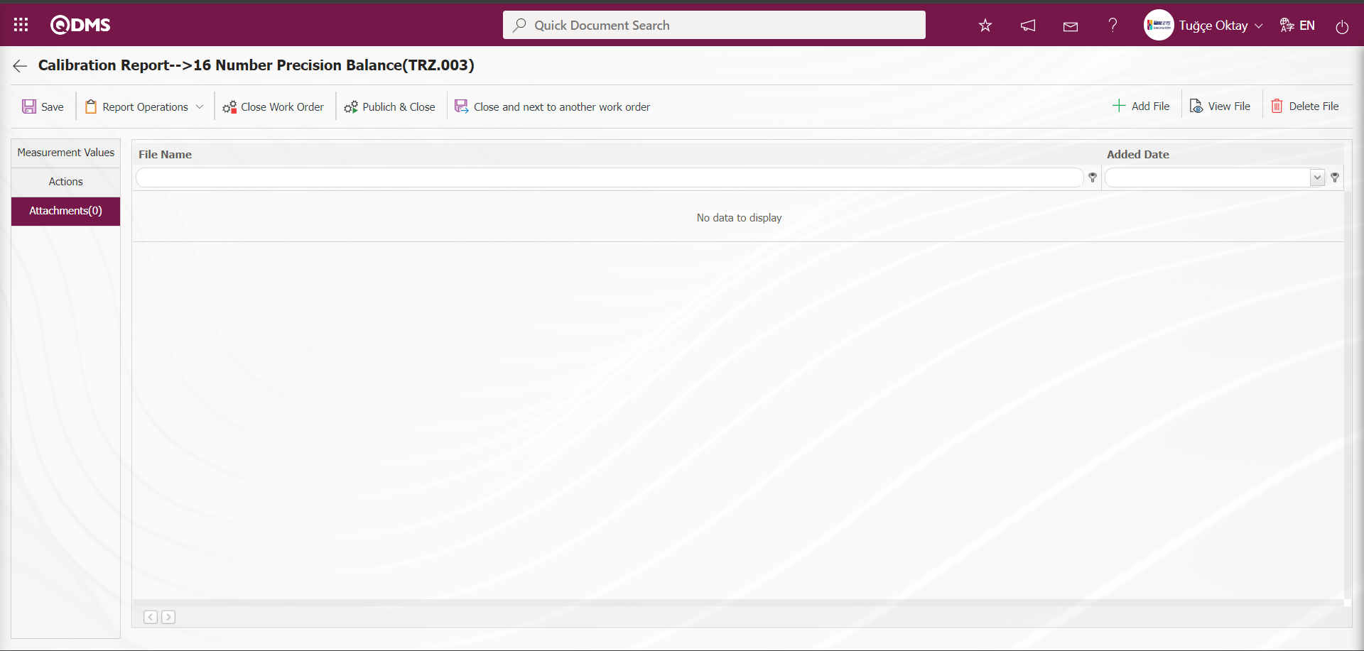
Using the buttons on the screen;
 : The additional file upload process is performed.
 : The selected additional file in the list is uploaded.
 : The selected additional file in the list will be deleted.
In the Calibration Report screen, click the button in the Additional Files tab to upload any additional files, such as measurement reports or certificates, related to the procedures performed on the device to the system.
Click on the Actions tab.

On the Calibration Report screen, after selecting the device action options in the device action field on the Operations screen, click the  button to prepare the Calibration Report. After the message indicating that the Calibration Report has been created appears on the screen, the Calibration Report can be viewed.
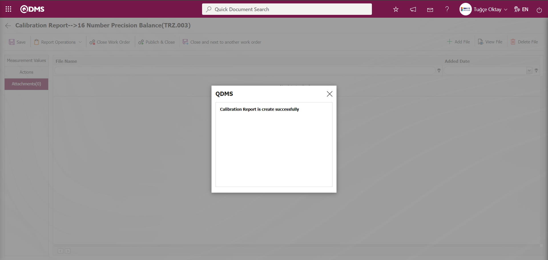
The system displays the message “Calibration Report is create successfully” to indicate that the transaction report has been created.

Using the buttons on the screen;
 : The calibration report preparation process is carried out.
 : After preparing the Calibration Report, the old report is deleted and a new report is created based on the updated information.
 : The Calibration Report is uploaded to the system from an external source.
 : The calibration report is displayed.
Click the button in the Actions tab on the Calibration Report screen.
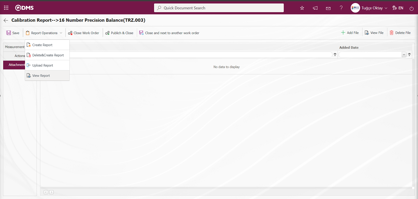
A calibration report is displayed in Excel format.
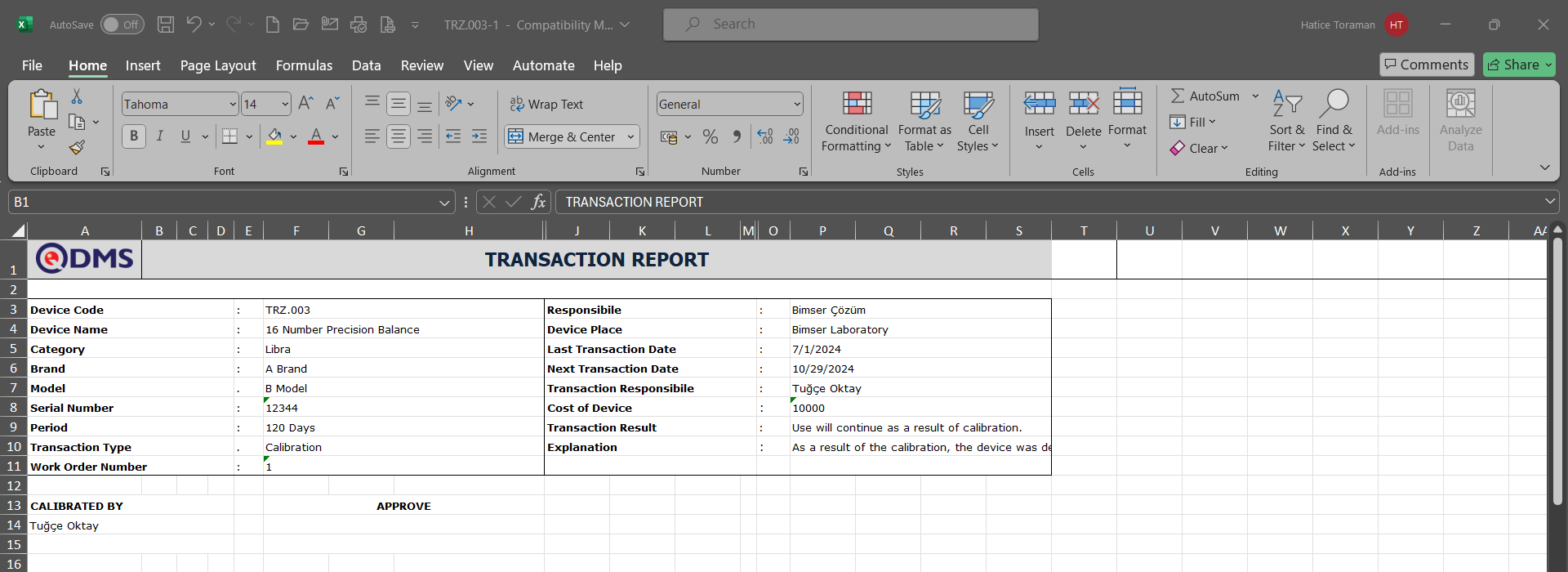
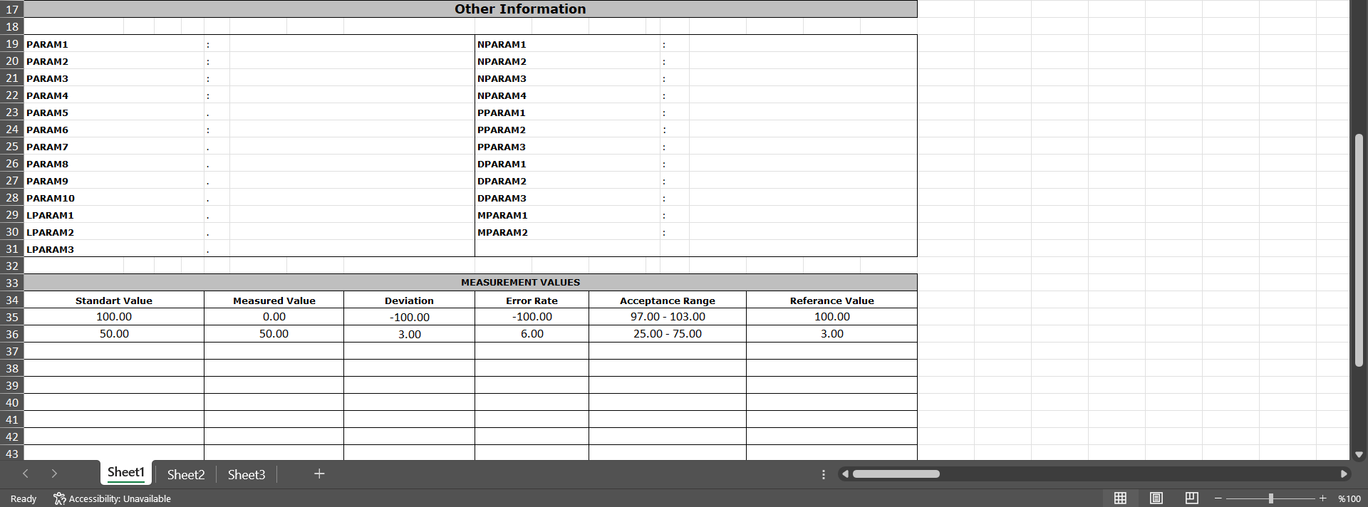
After the report is created/uploaded, there are two buttons to close the work order. The  button closes the work order without publishing it, and no email is sent to anyone. However, if the
  button is clicked, the work order is closed and an email is sent to the relevant persons.
Go to the “Work Order Closure Approval” definition under the “System Infrastructure Definitions/BSID/Configuration Settings/Flow Definition” menu, and use the button to assign roles for the flow. Select the relevant role from the list using the  button.
Click the button in the Operations tab on the Calibration Report screen.
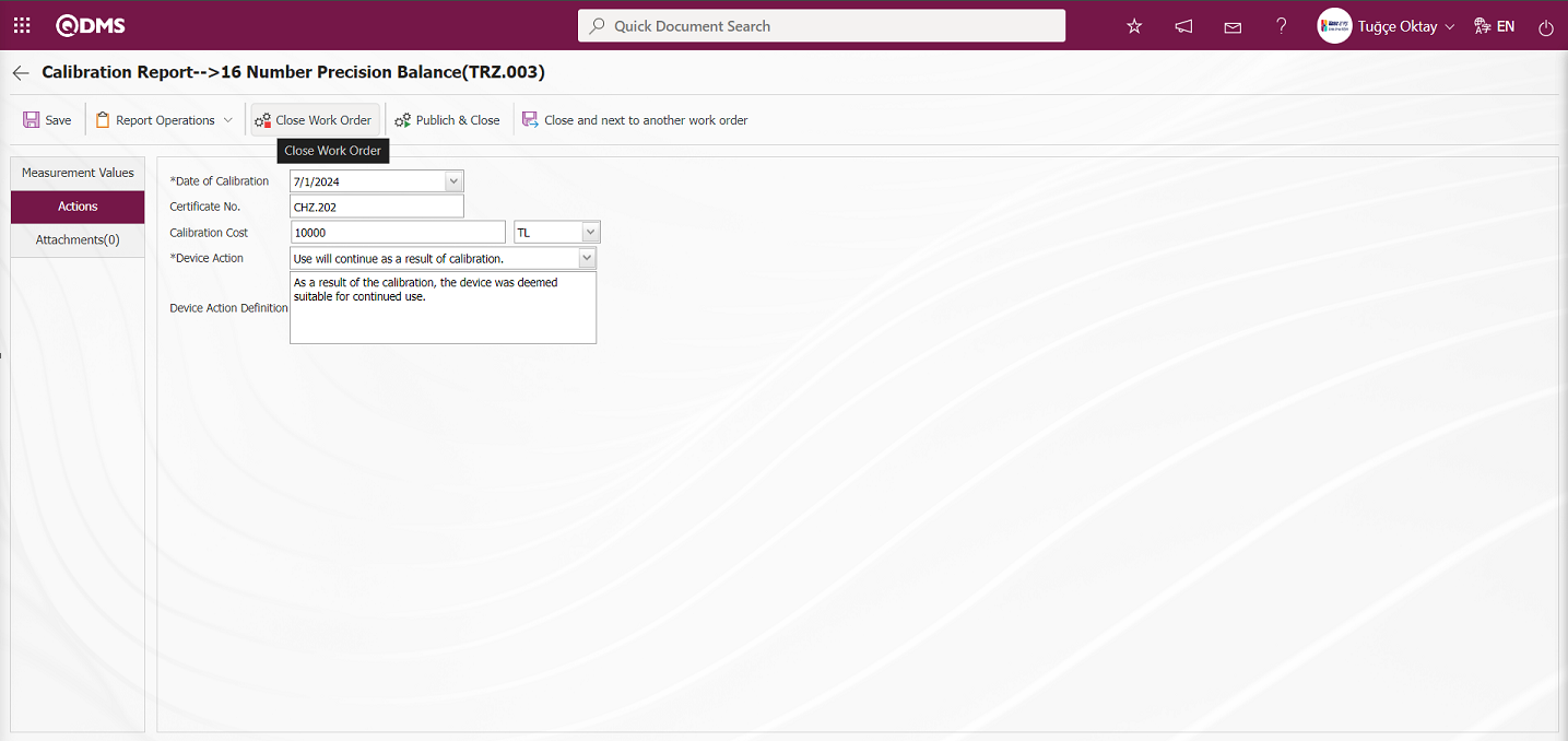
The work order is sent to the person for approval in the approval flow.
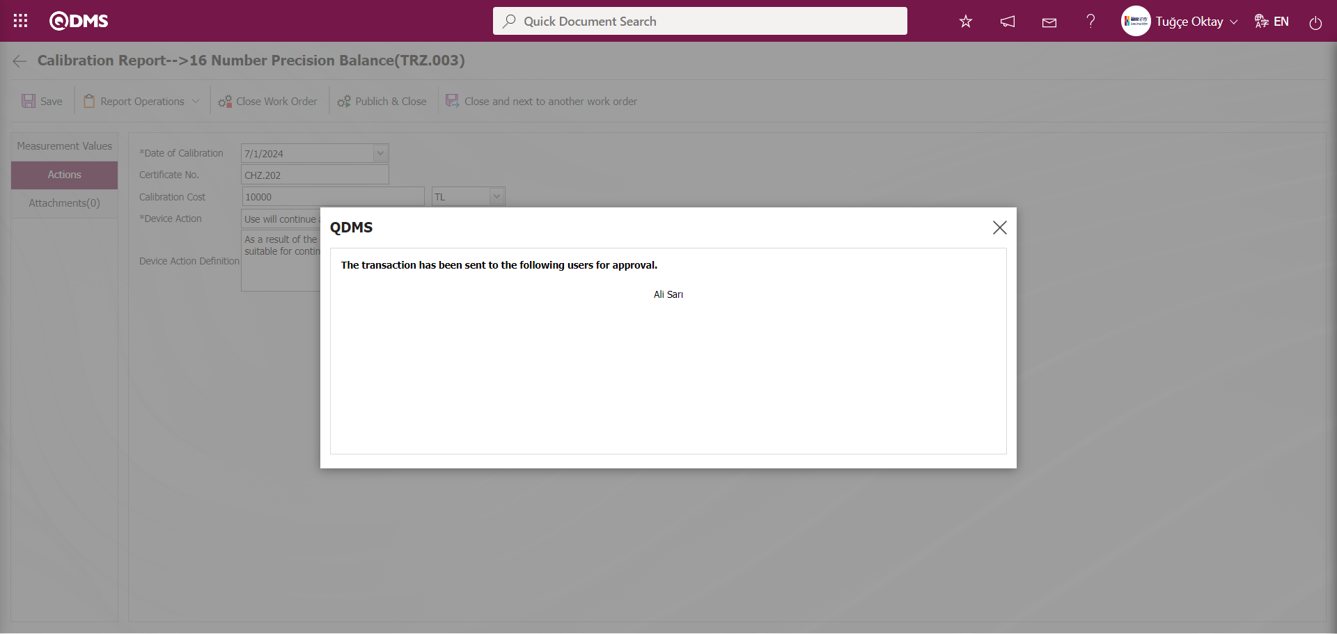
Log in to the local address using the username and password of the person in the approval flow from the Qdms main login screen.

The person in the approval flow will see the task “Closure Approval Pending Transactions” on their “My Pending Tasks” page.
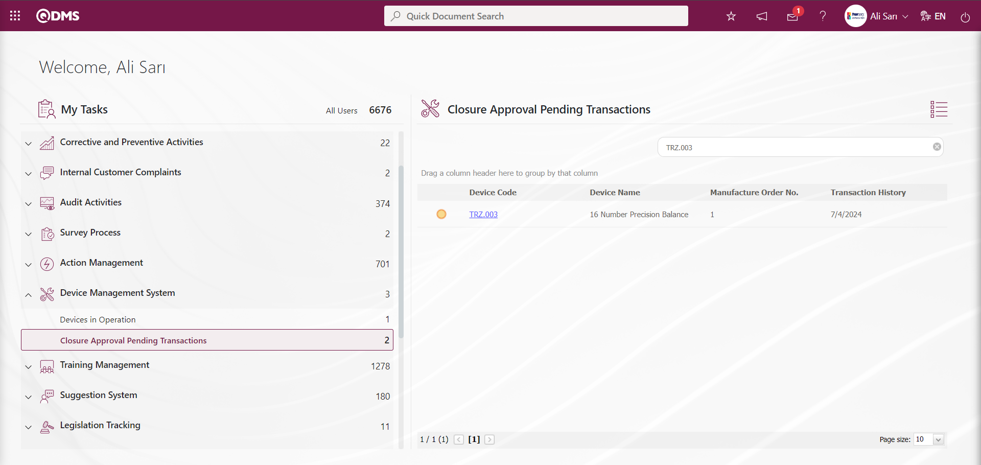
The person who approves clicks the link in the Device code field for the relevant task to display the Calibration Report screen.

Using the buttons on the screen;
 : The work order approval process is carried out.
 : The work order is rejected by writing the reason for rejection.
Measurement Values Tab: This tab displays the defined measurement values for the device, allows you to define new measurement values, update defined measurement values, and delete them. 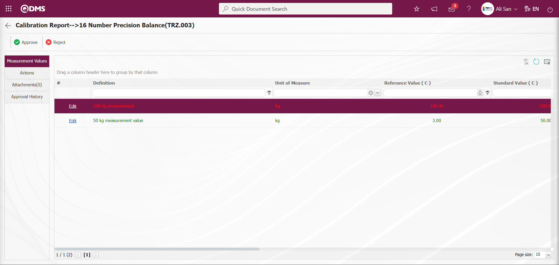
Actions Tab: This tab contains information such as the transaction date, certificate number, transaction cost, device action, and device action definition related to transactions performed on the device.
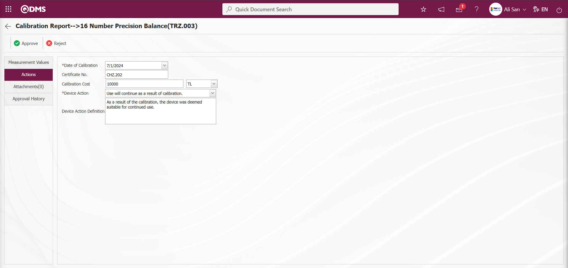
Attachments Tab: This tab is where you upload any additional files, such as measurement reports, certificates, invoices, and images, related to the procedures performed on the device to be added at this stage of the Calibration Report screen.
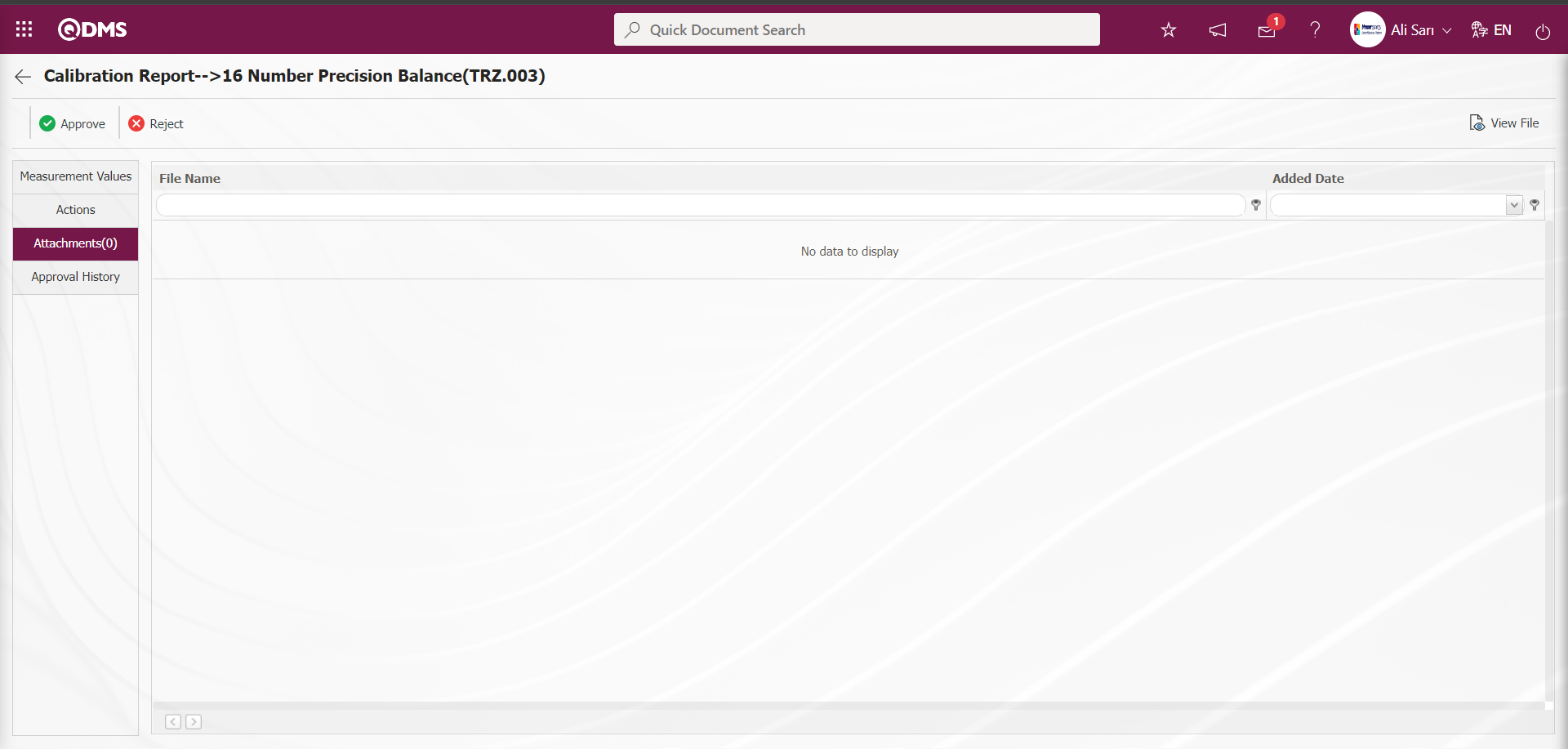
Using buttons on the screen;
 : The selected file in the list is displayed.
Approval History tab: This tab displays the approval history information, including the names and surnames of the approvers related to the device, the approval date, the approval status, and the approval description.
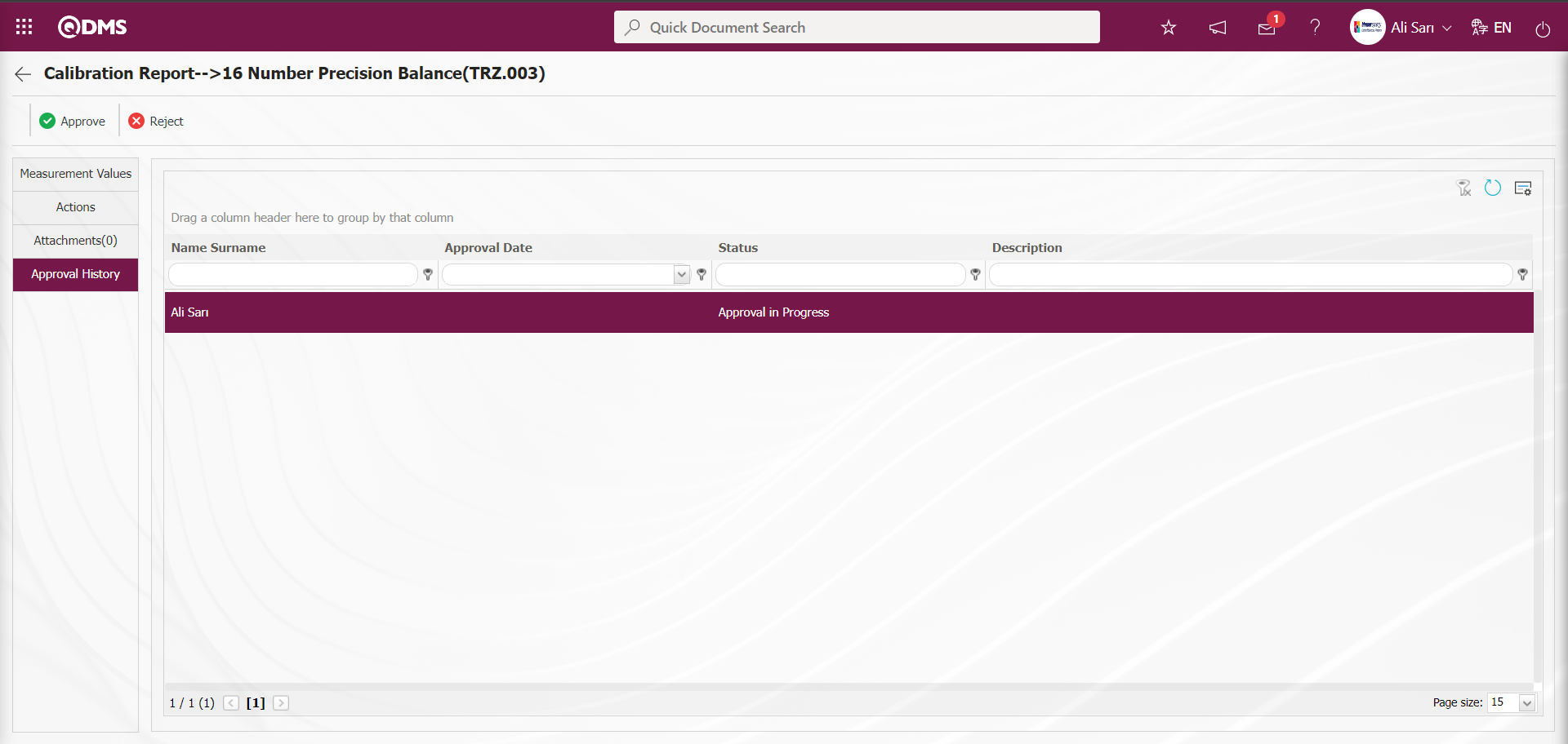
Click the  button on the Calibration Report screen.
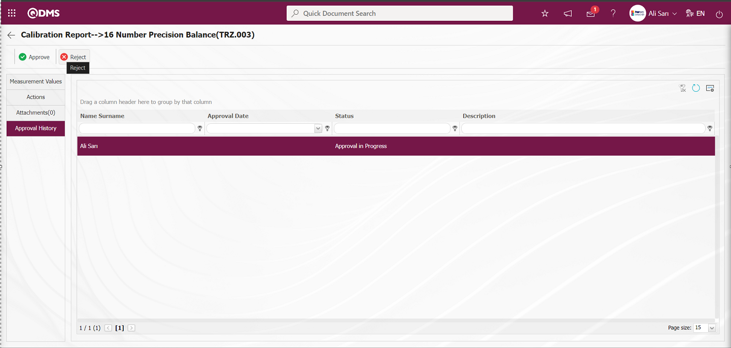
If desired, the rejection reason field in the Rejected Work Order screen can be filled in with the rejection reason for the work order to complete the rejection process.
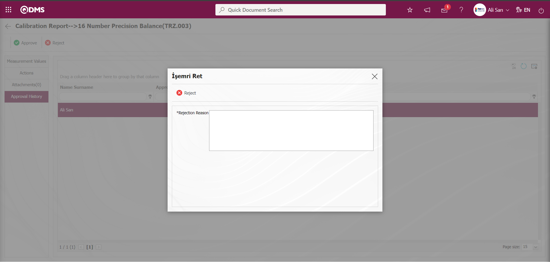
Click the  button on the Calibration Report screen.
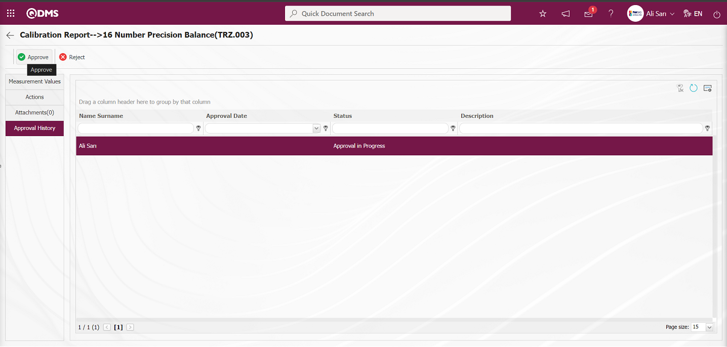
The work order is sent to the person in the approval flow for approval
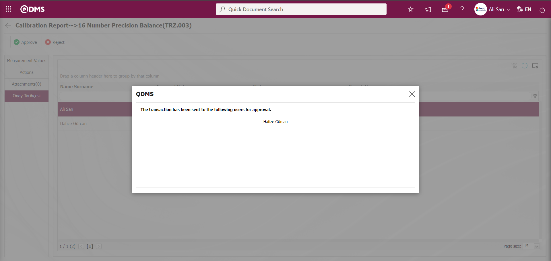
Log in to the local address using the username and password of the person in the approval flow from the Qdms main login screen.
The person in the approval flow will see the task “Closure Approval Pending Transactions” on their “Pending Tasks” page.
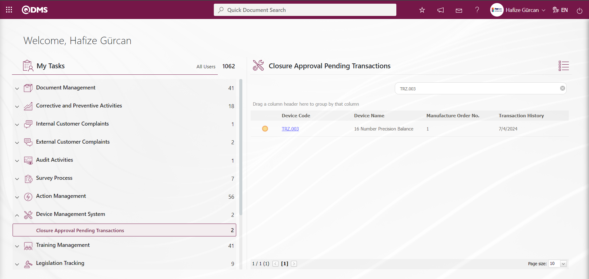
The person who approves clicks the link in the Device code field for the relevant task to display the calibration report screen.
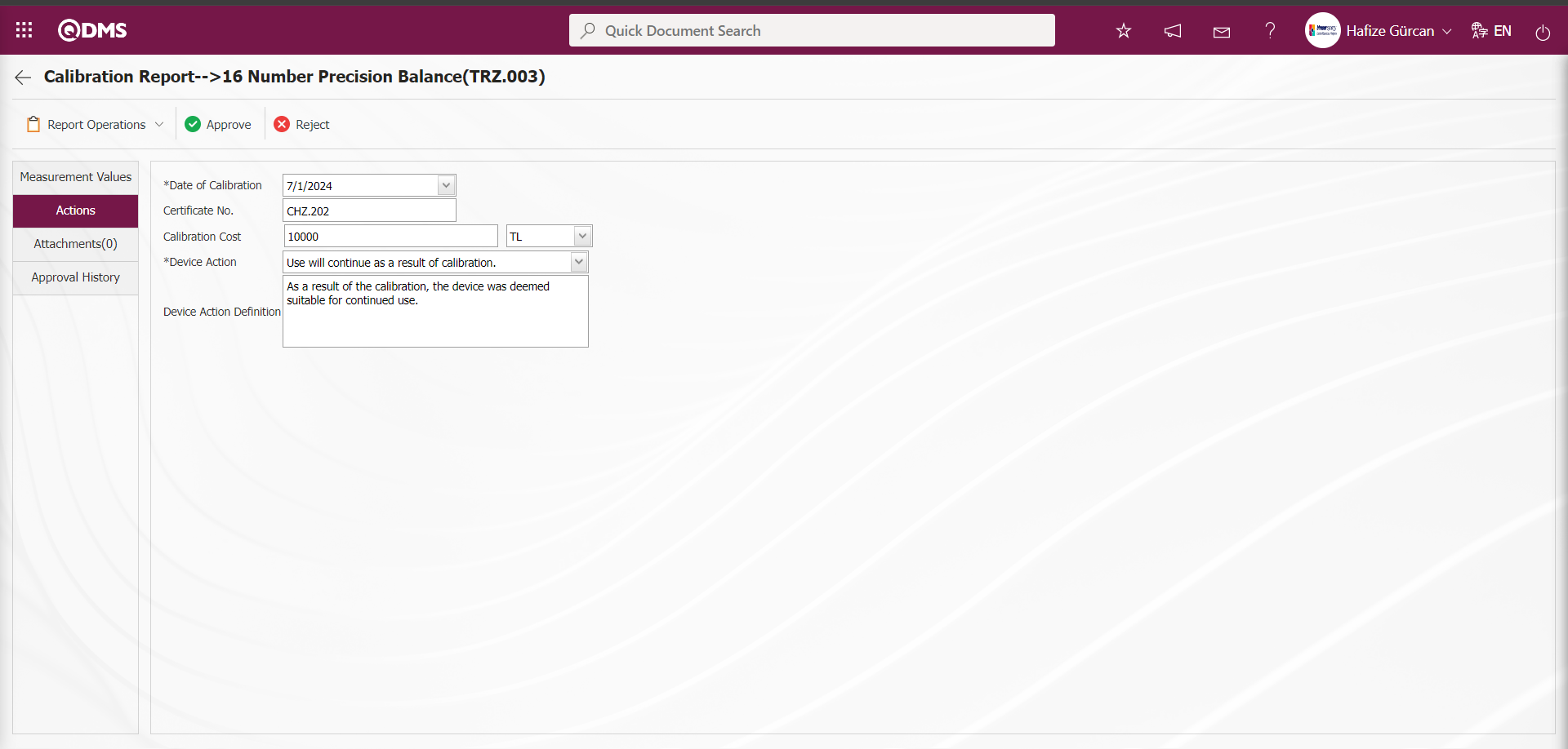
Using the buttons on the screen;
 : The steps related to report processing are carried out. These steps include:
  The calibration report can be viewed by clicking the button.
 : The work order approval process is carried out.
Measurement Values Tab: This tab displays the defined measurement values for the device, allows you to define new measurement values, update defined measurement values, and delete them.
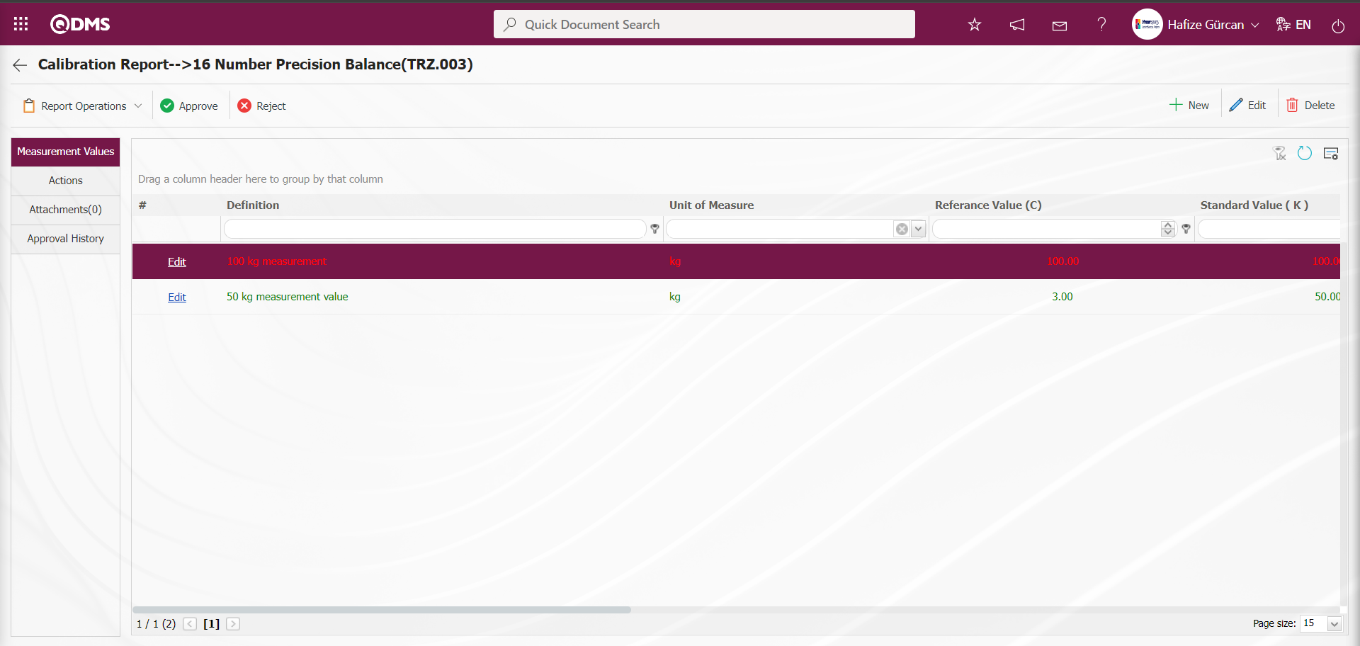
With the help of the buttons on the screen;
: A new measurement constant is defined.
: Edit and update the selected measurement constant information in the list.
: Delete the selected measurement constant information in the list.
: Return to the previous screen.
: Data can be exported to Excel.
: The search criteria on the menu screens are used to clean the data remaining in the filter fields in the grid where the search operation is performed.
: The menu screen is restored to its default settings.
: User-based designing is done on the menu screen with the show-hide feature, that is, the hiding feature of the fields corresponding to the columns on the menu screens.
Actions Tab: This tab contains information such as the transaction date, certificate number, transaction cost, device action, and device action definition related to transactions performed on the device.
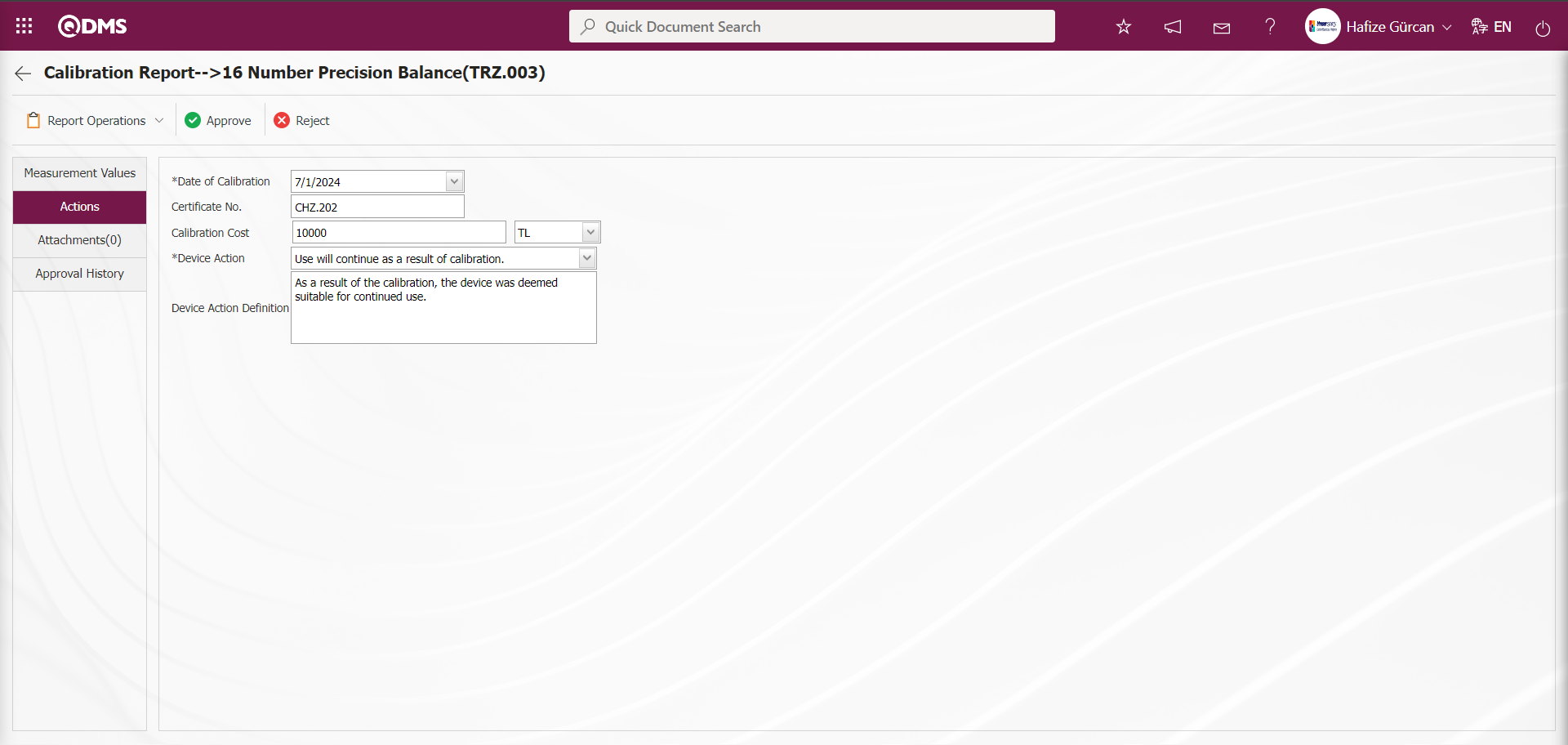
Attachments Tab: This tab is where you upload any additional files, such as measurement reports, certificates, invoices, and images, related to the procedures performed on the device to be added at this stage of the Calibration Report screen.

Using the buttons on the screen;
 : The additional file upload process is performed.
 : The selected additional file in the list is uploaded.
 : The selected additional file in the list will be deleted
Approval History tab: This tab displays the approval history information, including the names and surnames of the approvers related to the device, the approval date, the approval status, and the approval description.
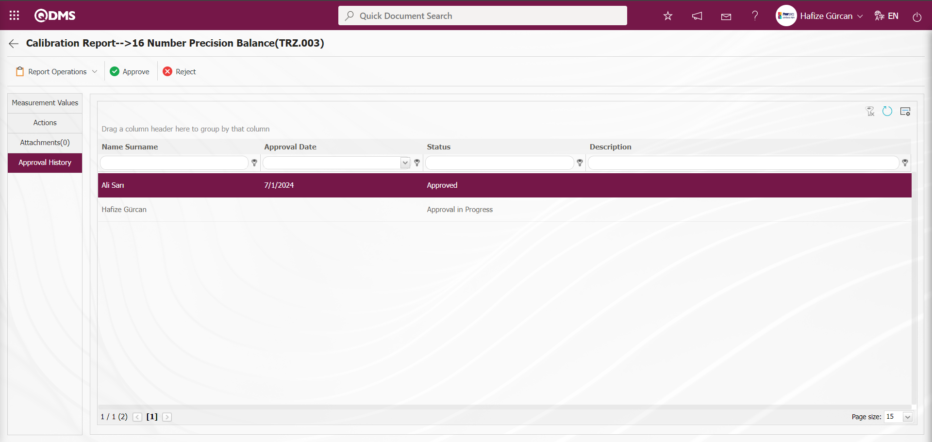
Click the  button on the Calibration Report screen.
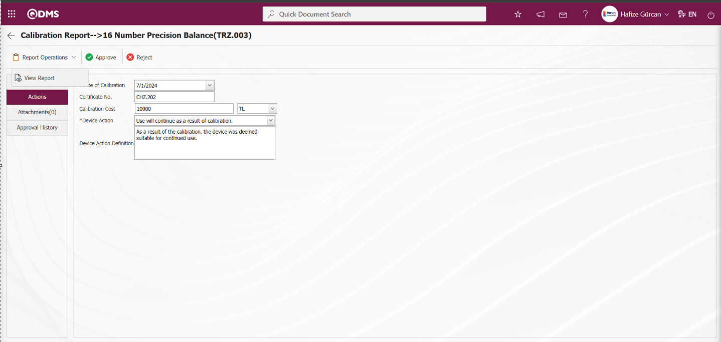
At this stage, the calibration report is displayed in Excel format.
Click the  button on the Calibration Report screen.
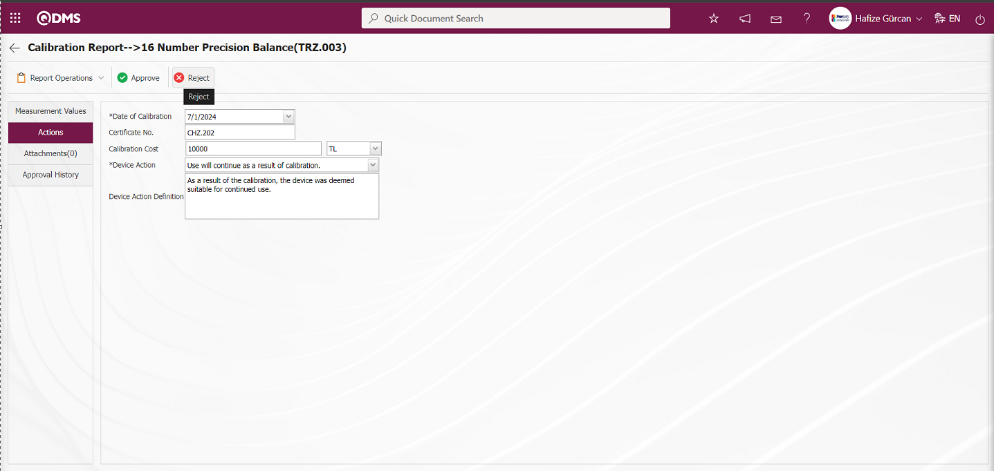
If desired, the rejection reason field in the Rejected Work Order screen can be filled in with the reason for rejection, and the rejection process is completed.
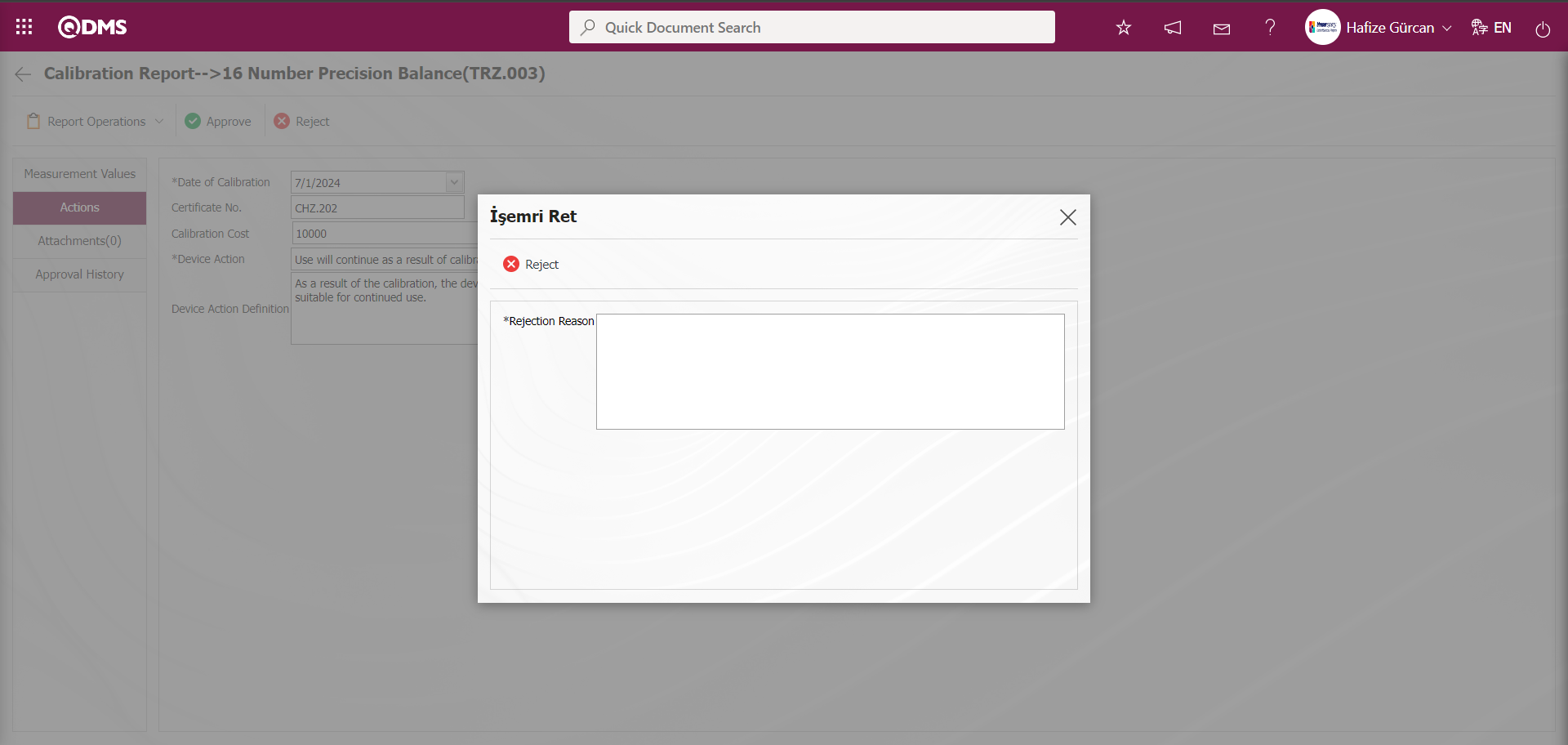
Click the button on the Calibration Report screen.
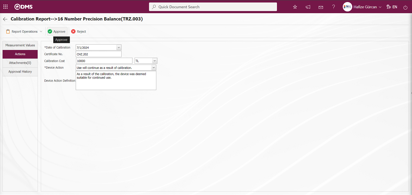
After clicking the  button on the Calibration Report screen, the work order is closed.
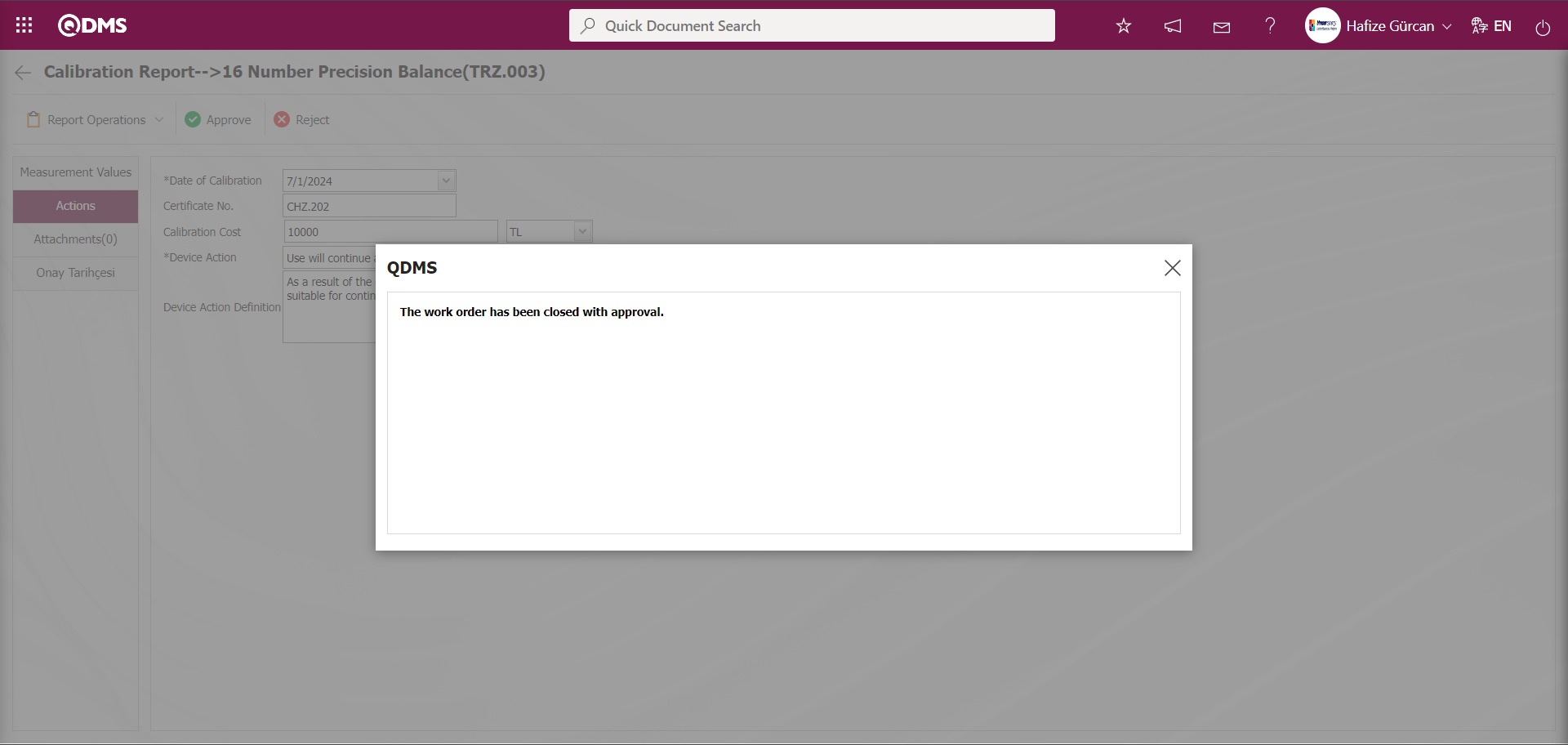
A message indicating that the work order has been closed by the system after approval is displayed.
6.2.3. Operation History
Menu Name: Integrated Management System/ Device Management/ Operation History
This menu is used to view the operation history of devices within the device management module. Clicking the Integrated Management System/Device Management/Operation History menu displays the Device List screen. The Device List screen displays two tabs: Filter and List. The List tab displays a list of devices defined in the system.
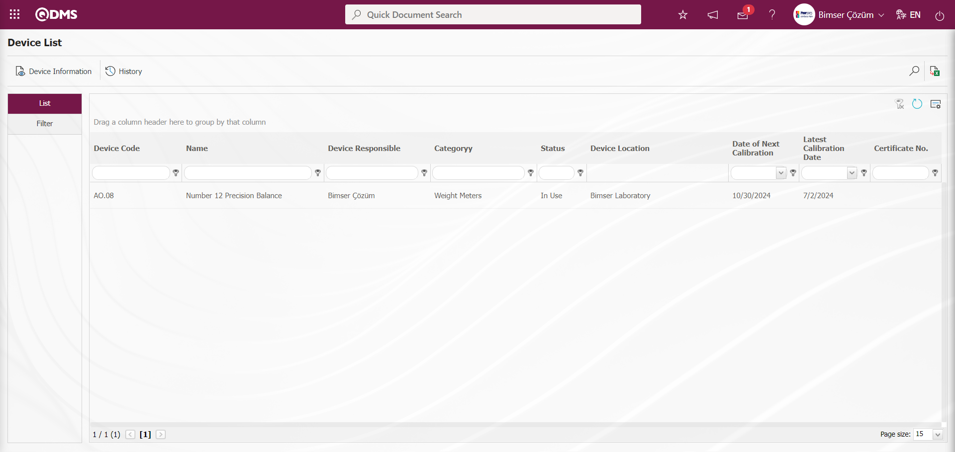
Using the buttons on the screen;
 : The information of the selected device in the list is displayed.
 : The history information of the selected device in the list is displayed.
In the Filter tab, data is entered or selected in the search criteria fields and filtering operations are performed according to the search criteria.
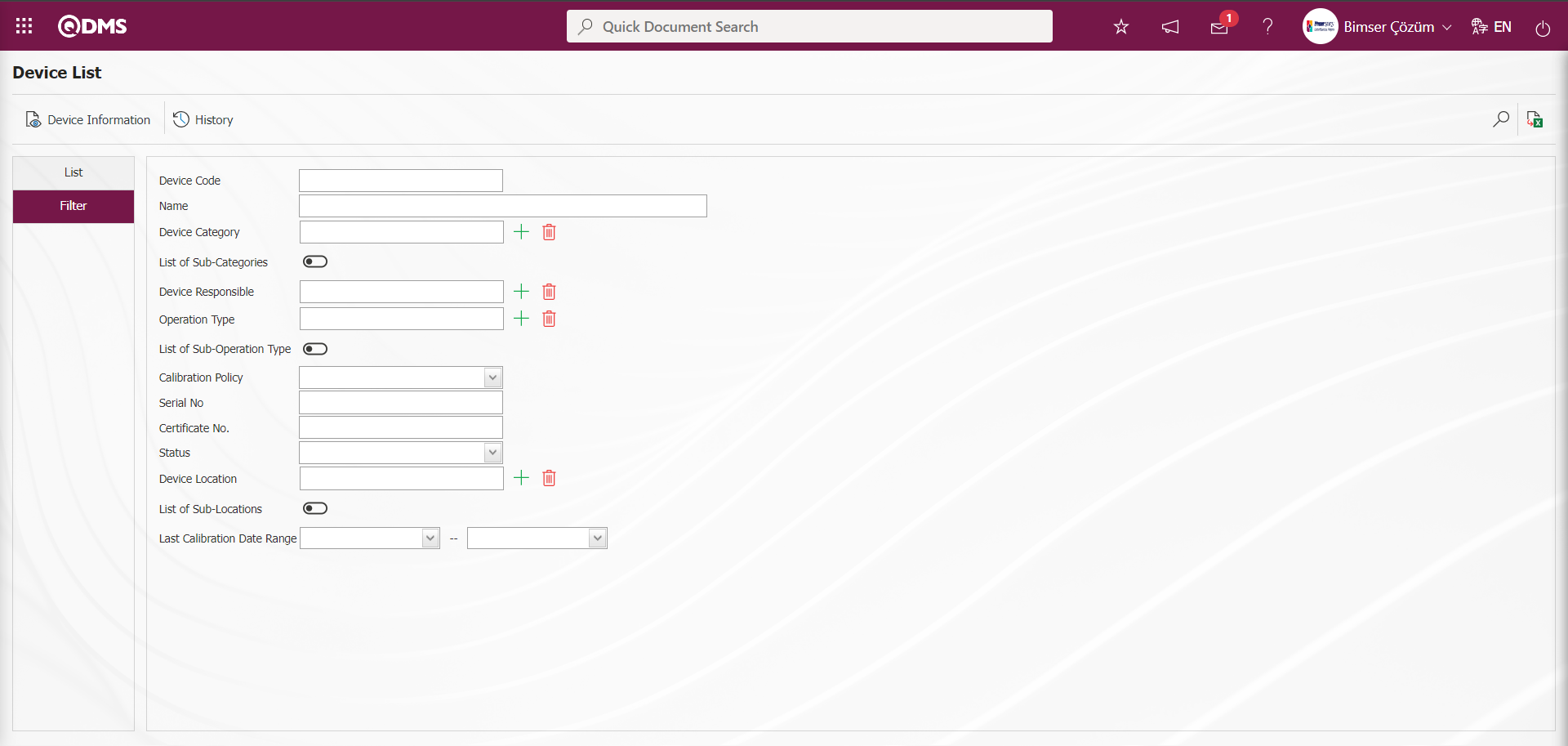
On the Device List screen, click the button while a device is selected in the list on the list tab.
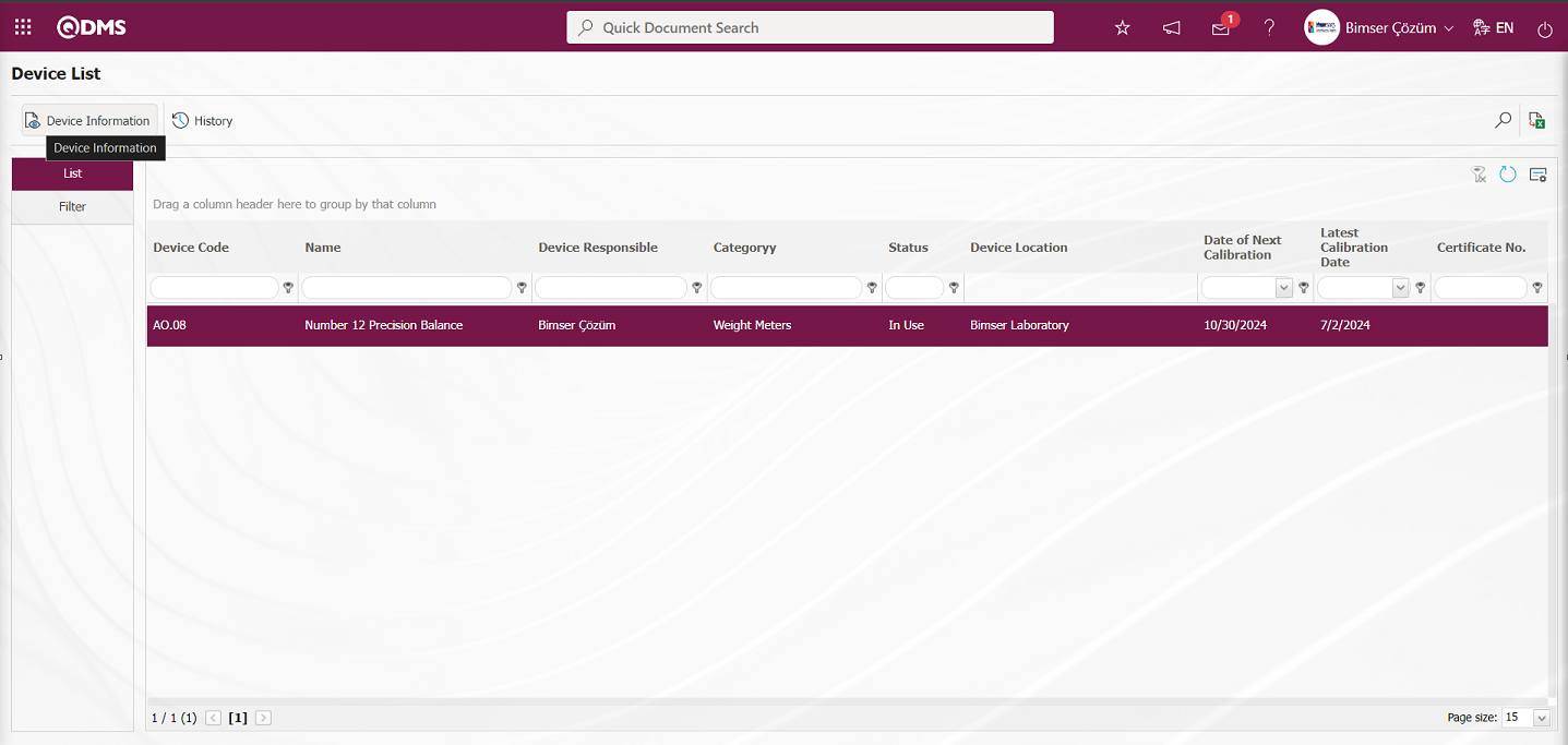
The Device Information screen opens. The screen displays two tabs: Device Information and Attachments. 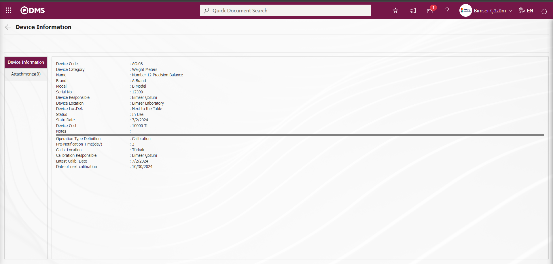
Device Information tab: This tab contains device information such as device code, device category, name, brand, and description of the operation type, as well as information about the types of operations performed on the device, such as the pre-notification period and operation location.

Attachments Tab: This tab displays any additional files, such as measurement reports and certificates, related to the operations performed on the device.

Using the buttons on the screen;
 : The selected additional file in the list is displayed.
 : Return to the previous screen.
On the Device List screen, click the  button while a device is selected in the list on the list tab.
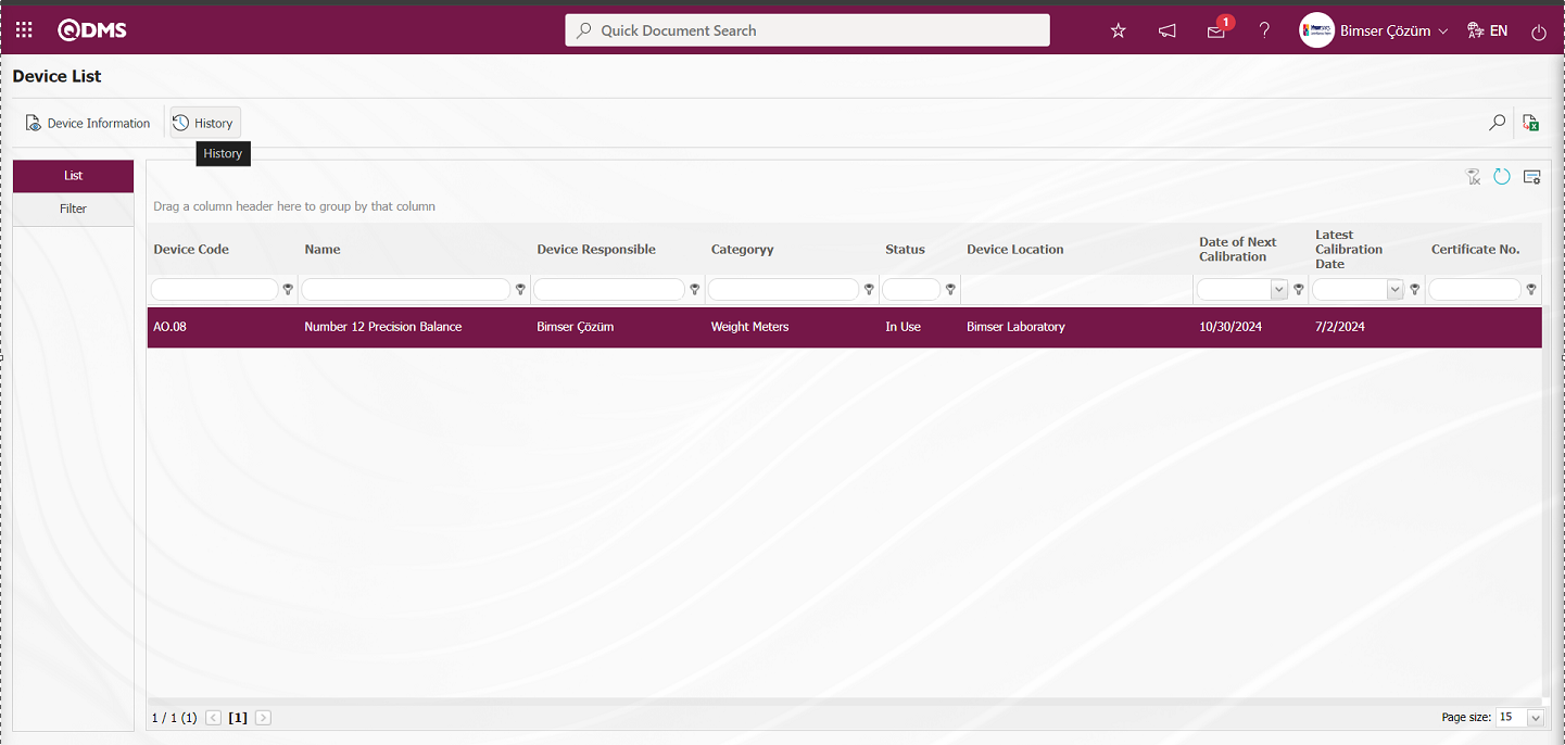
The Calibration History screen opens. This screen shows which process has been applied to which devices and how many times.
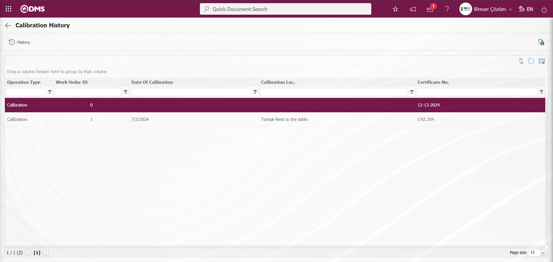
Using the buttons on the screen;
 : The device's processing history and information are displayed.
 : The data is transferred to Excel.
: The search criteria on the menu screens are used to clean the data remaining in the filter fields in the grid where the search operation is performed.
: The menu screen is restored to its default settings.
: User-based designing is done on the menu screen with the show-hide feature, that is, the hiding feature of the fields corresponding to the columns on the menu screens.
On the Calibration History screen, click the  button while the Operation Type is selected in the list.
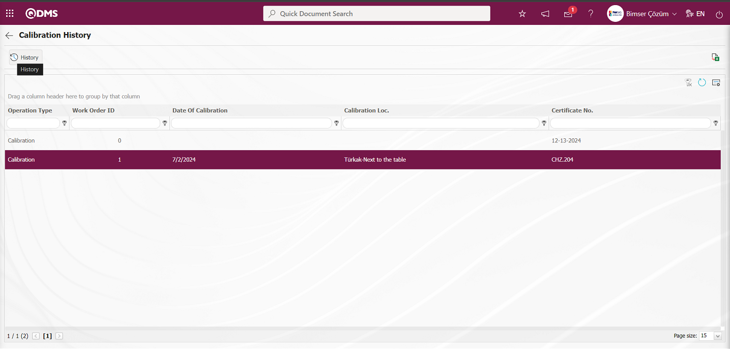 The Calibration History screen opens. This screen contains three tabs: History, Attachments, and Approval History.
History Tab: This tab contains information such as the device code, category, name, and device-specific operations. Clicking the  button at this stage allows you to download the calibration report for the device in Excel format.
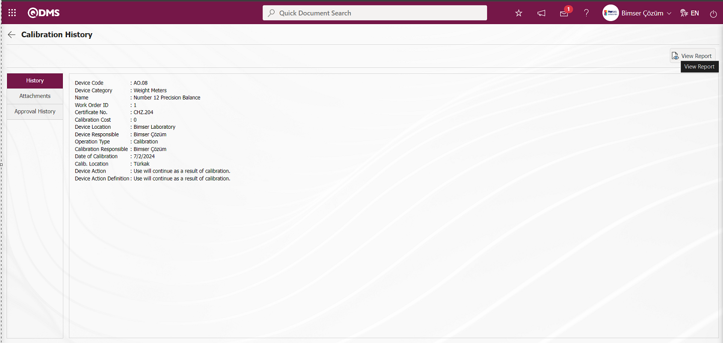
Using the buttons on the screen;
: The calibration report is displayed.
Click the button in the History tab of the Calibration History screen. The calibration report/certificate file for the selected process is downloaded to the computer.
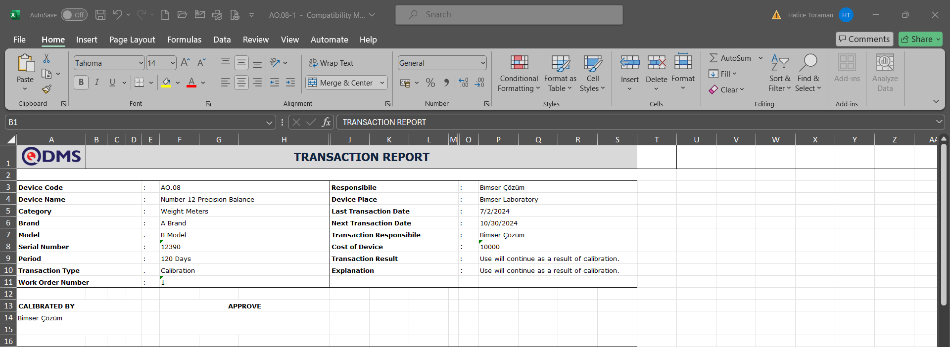
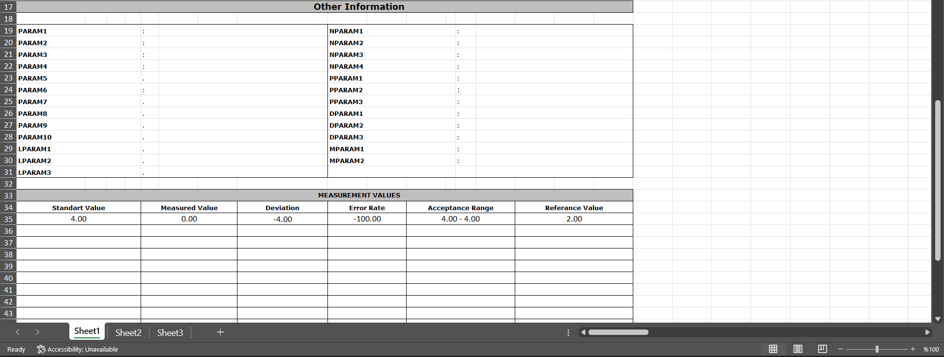
Attachments Tab: This tab displays measurement reports related to operations performed on the device and any additional files such as certificates, if available.

Using the buttons on the screen;
 : The selected file in the list is displayed.
Approval History tab: This tab displays the approval history information, including the names and surnames of the approvers related to the device, the approval date, the approval status, and the approval description.

6.2.4. Reports
Menu Name: Integrated Management System/Device Management/Reports
This section displays reports related to the Device Management System Module.
6.2.4.1. Planned Operation Report
Menu Name: Integrated Management System/Device Management/Reports/Planned Operation Report
This menu displays a report containing information such as device code, category, device responsible, process responsible, operation type, and period for planned operations. The screen that opens displays two tabs: Filter and List. In the Filter tab, data is entered into or selected from fields with search criteria, and filtering is performed based on these criteria. In the List tab, records are listed according to the filtering criteria applied in the Filter tab.
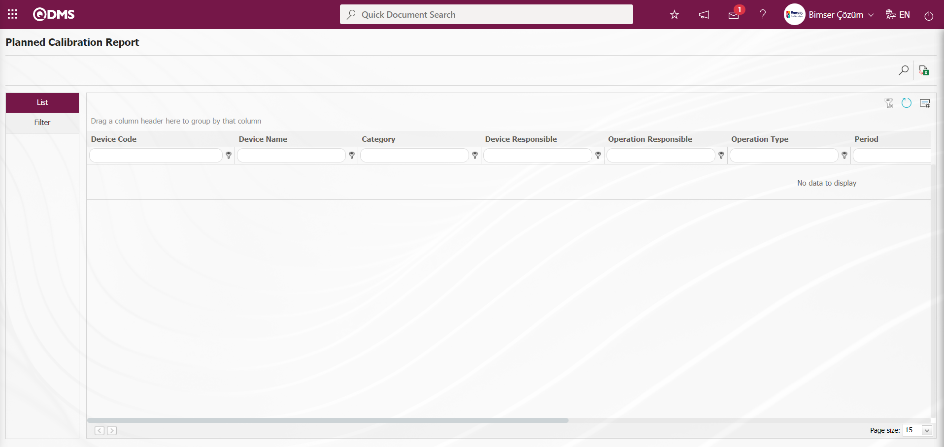
With the help of the buttons on the screen;
 : Records are filtered and searched.
 : Data is transferred to Excel.
 : The search criteria on the menu screens are used to clear the data remaining in the filter fields in the grid where the search operation is performed.
 : The menu screen is restored to its default settings.
 : User-based designing of the menu screen is done with the show-hide feature, that is, the hiding feature of the fields corresponding to the columns on the menu screens.
In the Planned Operation Report screen, in the Filter tab, enter the filter search criteria “Device Code” in the Device Code field and click the  (Search) button.
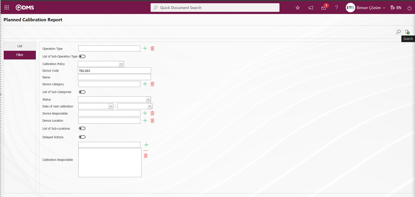
The records are listed according to the search criteria in the filter on the list tab of the Planned Calibration Report screen.
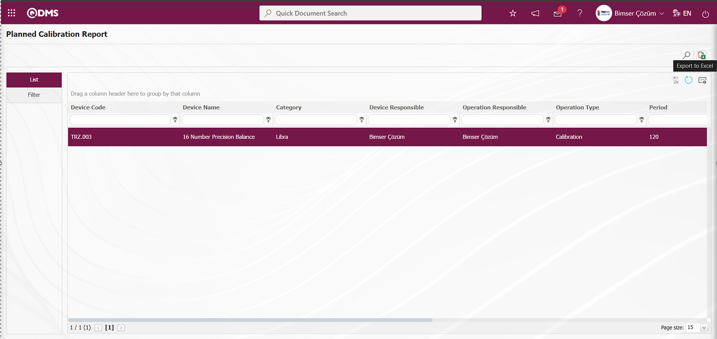
The Planned Calibration Report can be downloaded in Excel format by clicking the  (Export to Excel) button on the Planned Calibration Report screen.
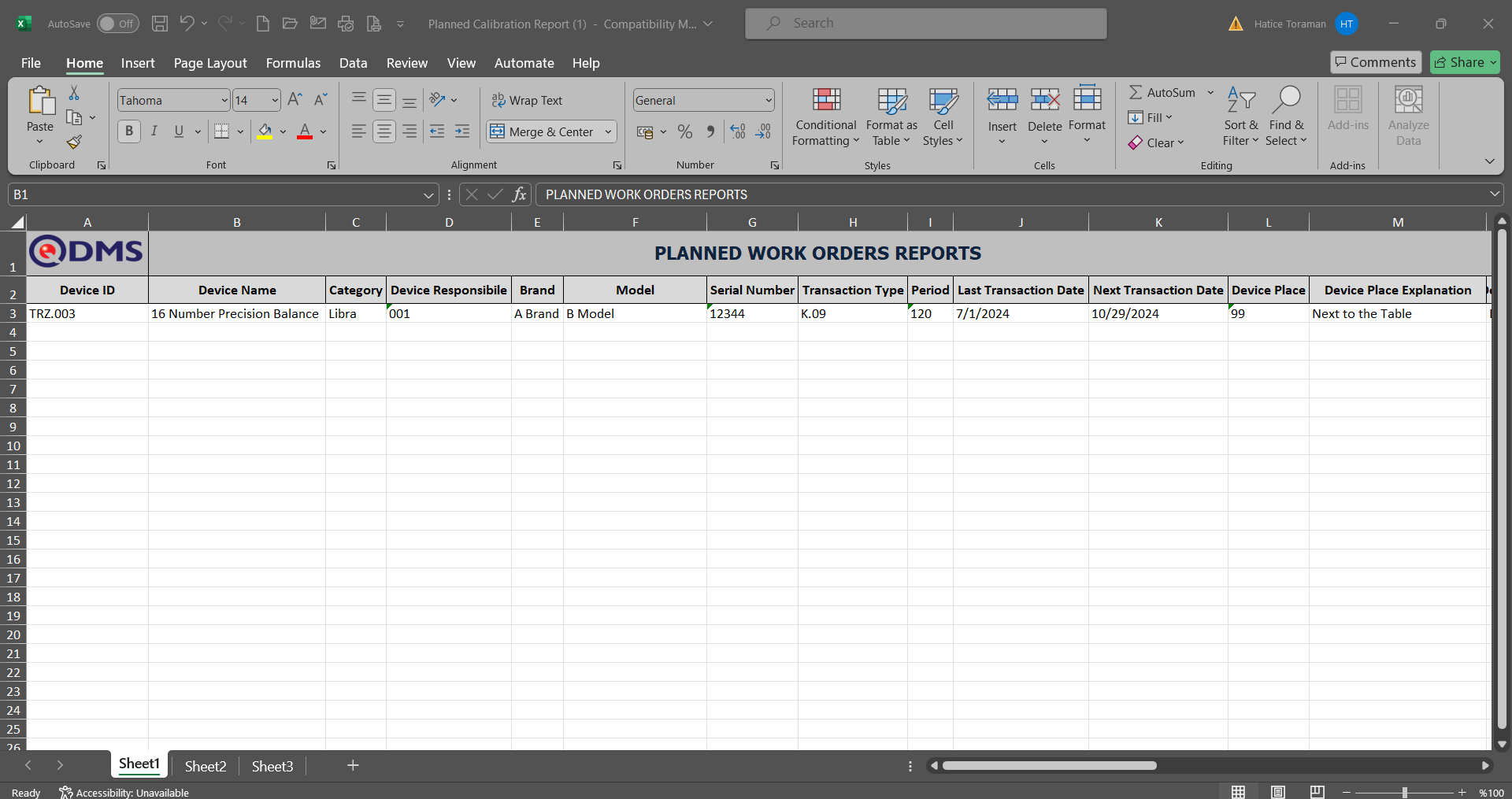
6.2.4.2. Report of Job orders
Menu Name: Integrated Management System/Device Management/Reports/Report of Job Orders
The Work Order Report is the menu where the most general report is obtained. It is a report where all work orders opened and closed in the system up to that point can be viewed and listed according to the desired filters. When the screen opens, two tabs appear: Filter and List. In the Filter tab, data is entered into or selected from the fields containing search criteria, and filtering is performed based on these criteria. In the List tab, records are listed according to the filtering criteria applied in the Filter tab.

With the help of the buttons on the screen;
: Records are filtered and searched.
: Data is transferred to Excel.
: The search criteria on the menu screens are used to clear the data remaining in the filter fields in the grid where the search operation is performed.
: The menu screen is restored to its default settings.
: User-based designing of the menu screen is done with the show-hide feature, that is, the hiding feature of the fields corresponding to the columns on the menu screens.
In the Work Order Report screen, in the Filter tab, enter the filter search criteria “Device Code” in the “Device Code” field and click the (Search) button.
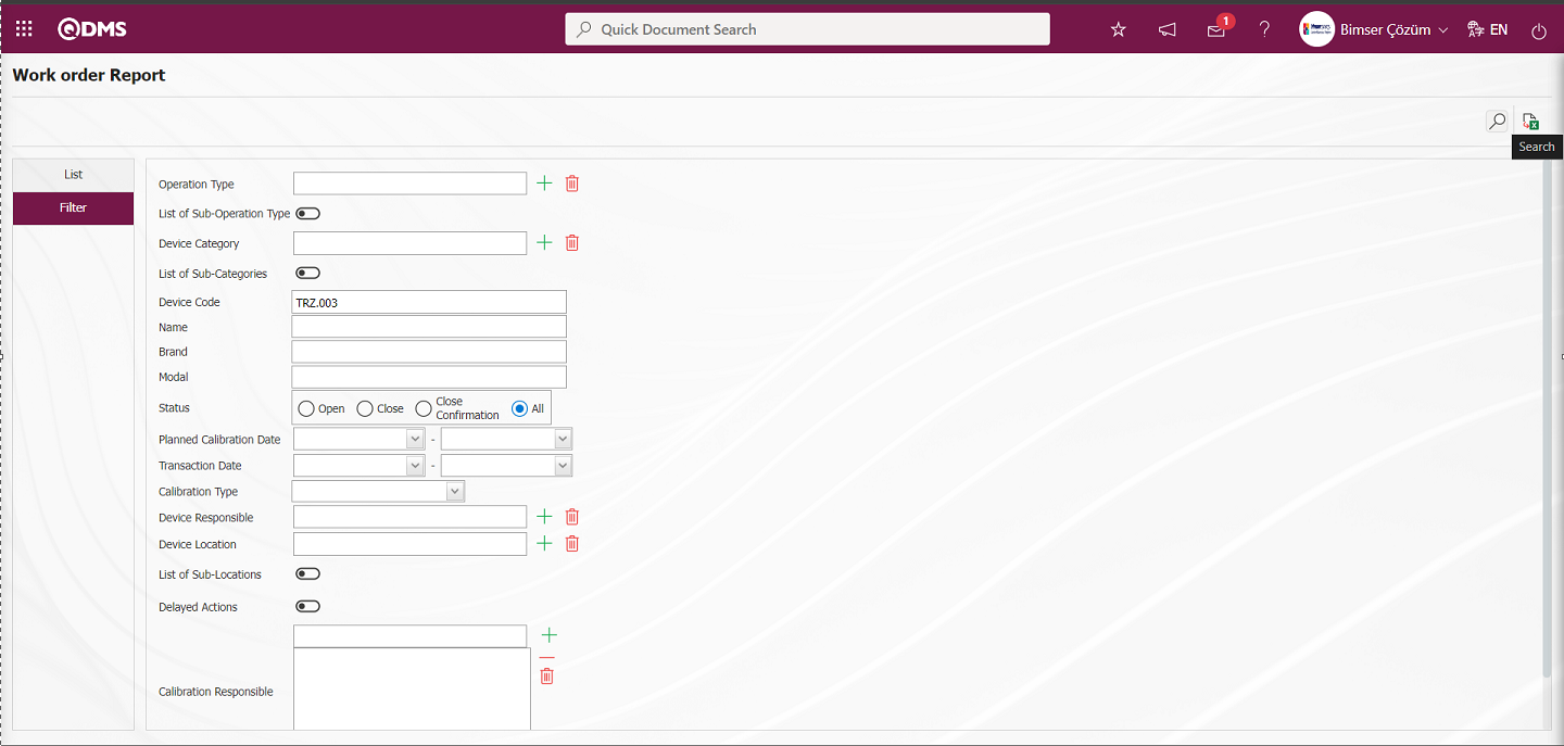
Records are listed according to the search criteria in the filter applied in the list tab of the Work Order Report screen.
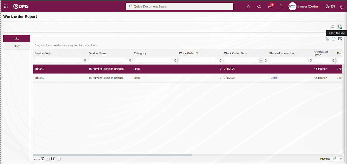
By clicking the (Export to Excel) button on the Work Order Report screen, you can download the work order report in Excel format.
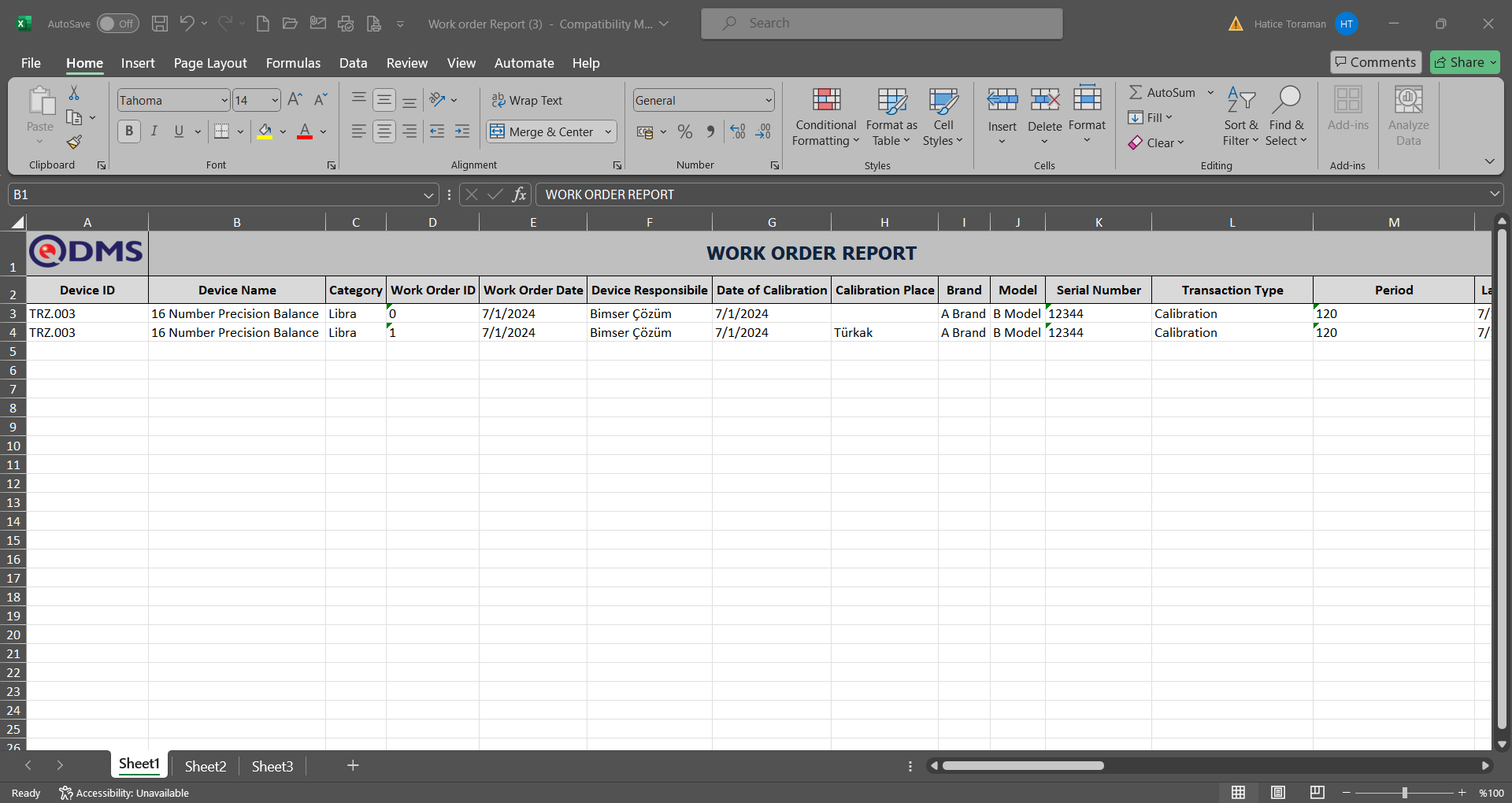
6.2.4.3. Device List
Menu Name: Integrated Management System/Device Management/Reports/Device List
The Work Order Detail Report is similar to the Work Orders Report. Additionally, measurement values are included. The screen that opens displays two tabs: Filter and List. In the Filter tab, data is entered into or selected from the fields containing search criteria, and filtering is performed based on these criteria. In the List tab, records are listed according to the filtering criteria specified in the fields.
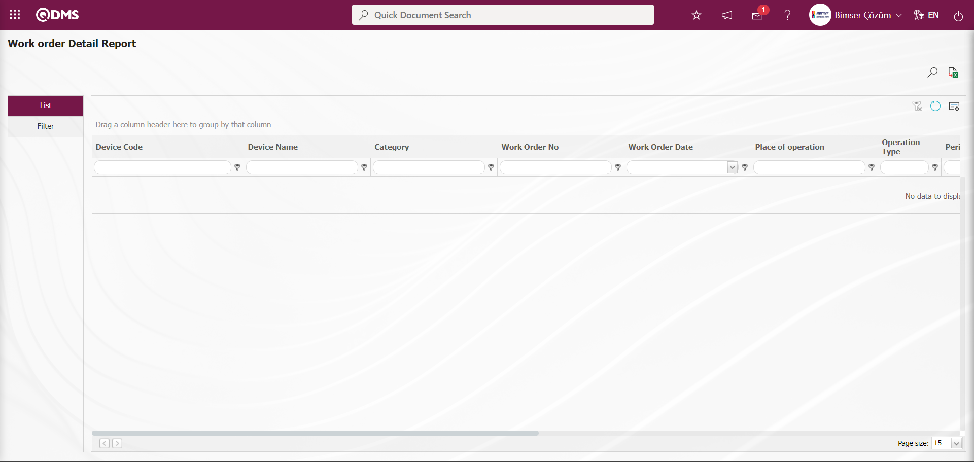
With the help of the buttons on the screen;
: Records are filtered and searched.
: Data is transferred to Excel.
: The search criteria on the menu screens are used to clear the data remaining in the filter fields in the grid where the search operation is performed.
: The menu screen is restored to its default settings.
: User-based designing of the menu screen is done with the show-hide feature, that is, the hiding feature of the fields corresponding to the columns on the menu screens.
In the Work Order Detail Report screen, click the  (Search) button in the “Device Code” field of the Filter tab, which contains the filter search criteria.

Records are listed according to the search criteria in the filter applied in the list tab of the Work Order Detail Report screen.
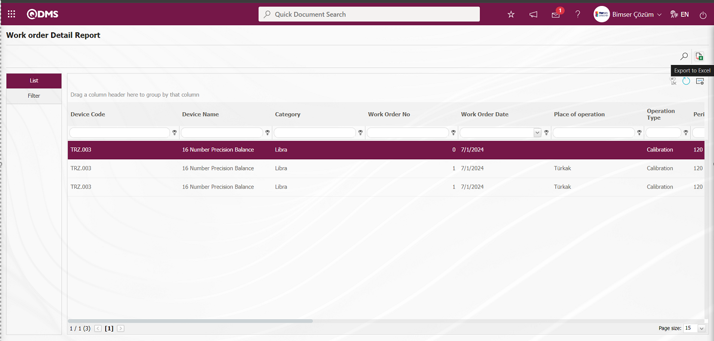
By clicking the (Export to Excel) button on the Work Order Detail Report screen, the Work Order Detail Report can be downloaded in Excel format.
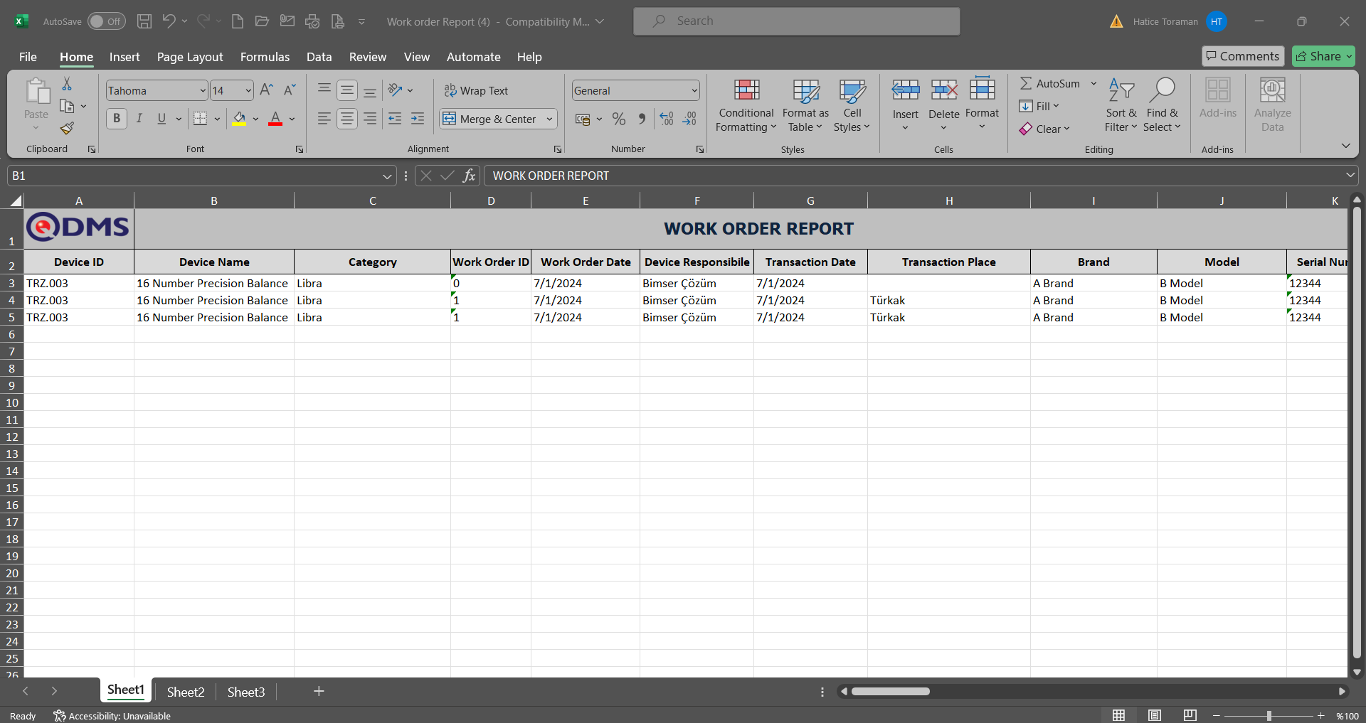
Measurement values are displayed in the report.
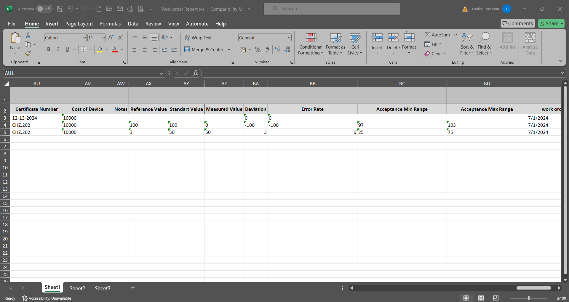
6.2.4.4. Cost Report
Menu Name: Integrated Management System/Device Management/Reports/Cost Report
This menu displays a report containing device and process cost information. The screen that opens contains two tabs: Filter and List. In the Filter tab, data is entered or selected in the fields corresponding to the search criteria, and the data is filtered according to the search criteria. In the List tab, the records are listed according to the filtering performed based on the search criteria.
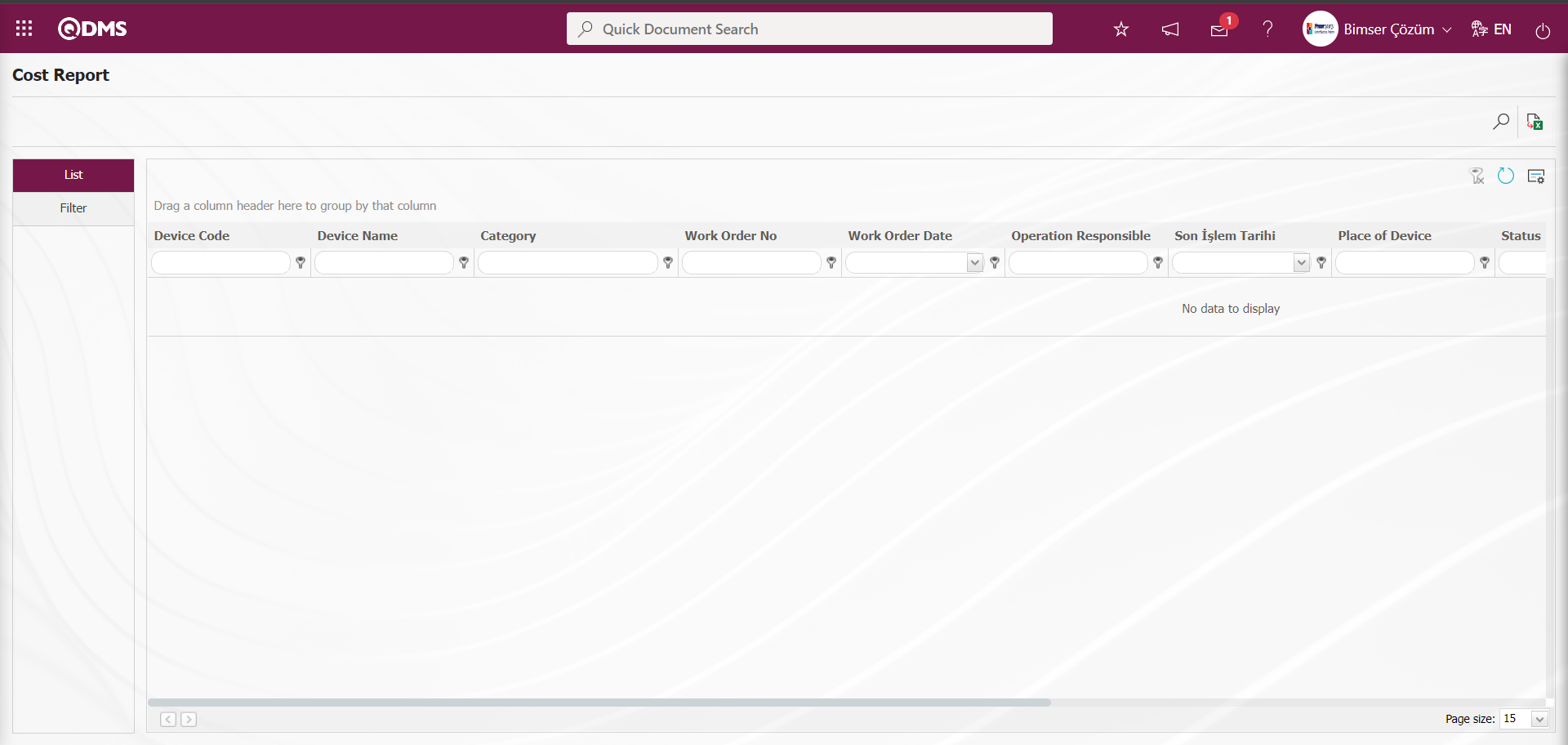
With the help of the buttons on the screen;
: Records are filtered and searched.
: Data is transferred to Excel.
: The search criteria on the menu screens are used to clear the data remaining in the filter fields in the grid where the search operation is performed.
: The menu screen is restored to its default settings.
: User-based designing of the menu screen is done with the show-hide feature, that is, the hiding feature of the fields corresponding to the columns on the menu screens.
On the Cost Report screen, in the Filter tab, enter the filter search criteria “Device Code” in the Device Code field and click the (Search) button.

Records are listed according to the search criteria in the filter on the list tab of the Cost Report screen. 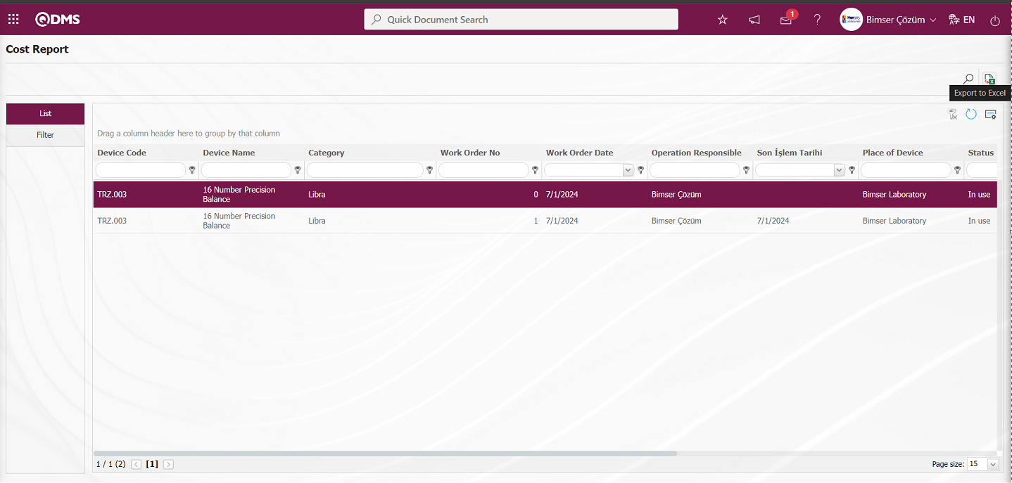
Click the (Export to Excel) button on the Cost Report screen to export the cost report in Excel format.

6.2.4.5. Approval Status Report
Menu Name: Integrated Management System/Device Management/Reports/Approval Status Report
This menu displays a report containing the status information of devices and processes awaiting approval, including information such as device code, device name, process type, process order number, and approver. When the screen opens, two tabs appear: Filter and List. In the Filter tab, data is entered into or selected from the fields containing search criteria, and filtering is performed based on these criteria. In the List tab, records are listed according to the filtering criteria applied in the Filter tab..

With the help of the buttons on the screen;
: Records are filtered and searched.
: Data is transferred to Excel.
: The search criteria on the menu screens are used to clear the data remaining in the filter fields in the grid where the search operation is performed.
: The menu screen is restored to its default settings.
: User-based designing of the menu screen is done with the show-hide feature, that is, the hiding feature of the fields corresponding to the columns on the menu screens.
On the Approval Status Report screen, in the Filter tab, enter the device code in the “Device Code” field of the filter search criteria and click the (Search) button.
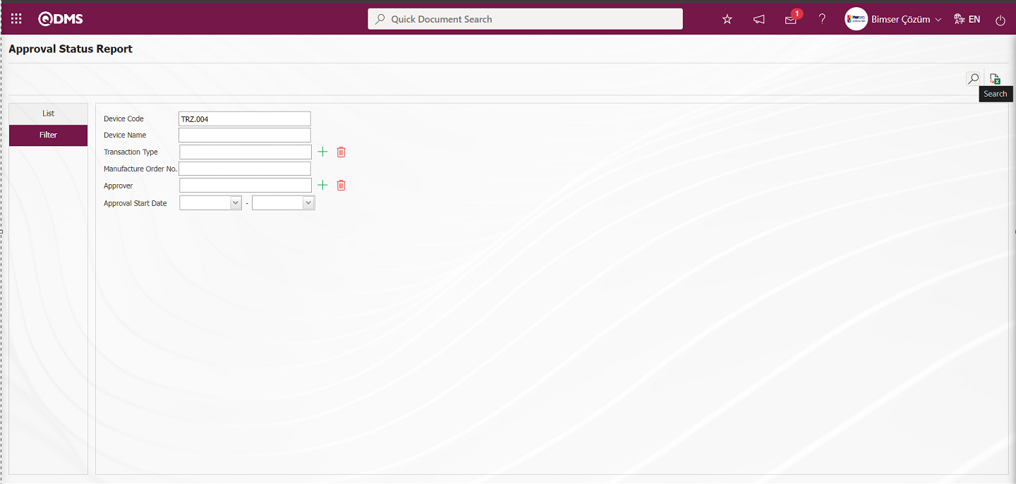
Records are listed according to the search criteria in the filter on the List tab of the Approval Status Report screen.

By clicking the  (Export to Excel) button on the Approval Status Report screen, the Approval Status report can be downloaded in Excel format.
6.2.4.6. Approve Control
Menu Name: Integrated Management System/Device Management/Reports/Approve Control
This report verifies who approved the device and when using the approval control code. In the approval control screen, entering the code information into the approval code field provides details such as the system-generated device number, the work order number, the date, time, and the person who approved it.
Using the buttons on the screen, you can:
 : Filter records to perform a search.
6.2.4.7. Timetable Report
Menu Name: Integrated Management System/Device Management/Reports/Timetable Report
This report visually displays the information regarding the tasks that process owners must perform on a monthly basis. It shows which task order is assigned to which owner on which day. When the screen opens, two tabs appear: Device Management List and Device Management Filter. In the Device Management Filter tab, data is entered or selected into the fields with search criteria, and filtering is performed based on these criteria. In the Device Management List tab, records are listed according to the filtering criteria applied in the search criteria fields.
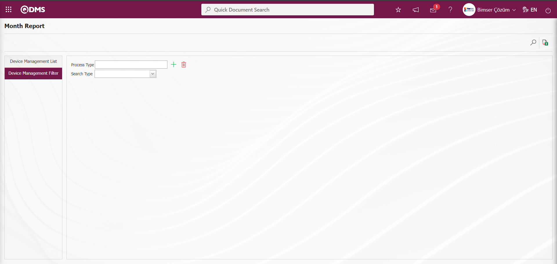
With the help of the buttons on the screen;
: Records are filtered and searched.
: Data is transferred to Excel.
In the Device Management Filter section, click the  (Select) button in the Process Type field to open the list of process types defined in the system and select the process type. In the Search Type field, select User Group from the Department and User Group options. In the User Group selection process, click the (Select) button in the displayed field to open the system-defined User Group list, make a selection, and then click the
  (Search) button.
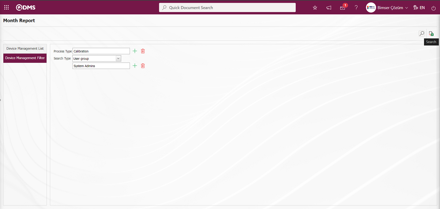
The records are listed according to the search criteria in the filter in the Device Management List tab on the Time Schedule Report screen. A calendar is displayed in the Device Management List tab. The month and year can be selected at the top. The days are displayed at the bottom of the calendar, and the persons assigned as the persons responsible for the operations are displayed on the left side of the calendar. The days with the Planned Operation Date are marked.
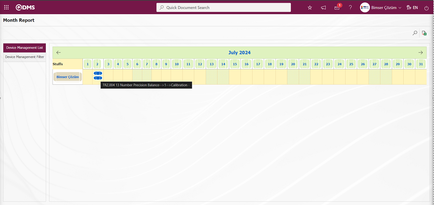
Click the (Export to Excel) button on the Monthly Report screen.
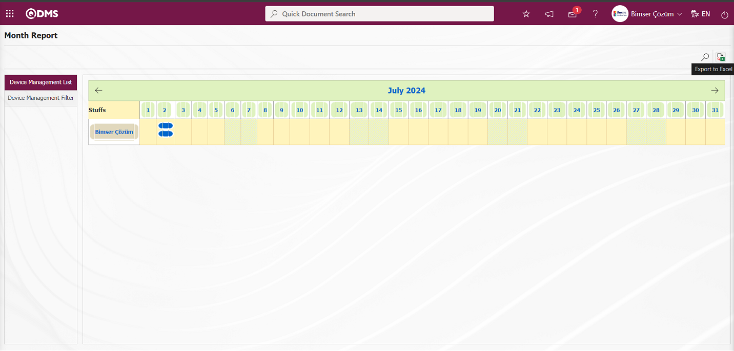
The timetable report is obtained from the Excel format of the timetable report.